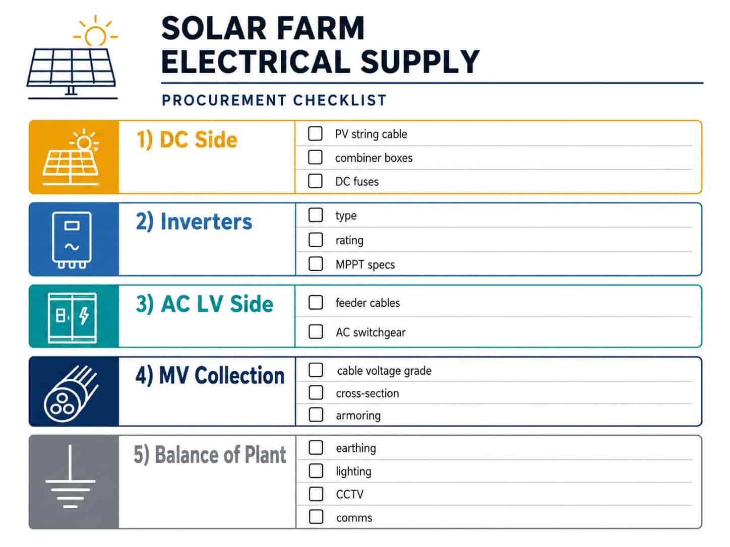
Utility-scale solar farm projects involve one of the most distinct electrical procurement packages in the renewable energy sector. Unlike conventional industrial or commercial electrical supply, solar farm procurement spans two voltage domains — a DC side from panels to inverters, and an AC side from inverters to the grid — with specialist cable types, high-voltage collection systems, and a balance-of-plant that includes earthing, monitoring, and auxiliary power supply.
This guide covers the major electrical procurement categories for a utility-scale solar PV project, from string cables in the panel field to the medium voltage collection network and grid connection point. It is written for EPC contractors, project procurement managers, and B2B buyers sourcing electrical products from China for solar farm construction.
Solar Farm Power Architecture
Understanding the power flow from panel to grid is the foundation for organizing the procurement package. A typical utility-scale solar farm electrical architecture follows this sequence: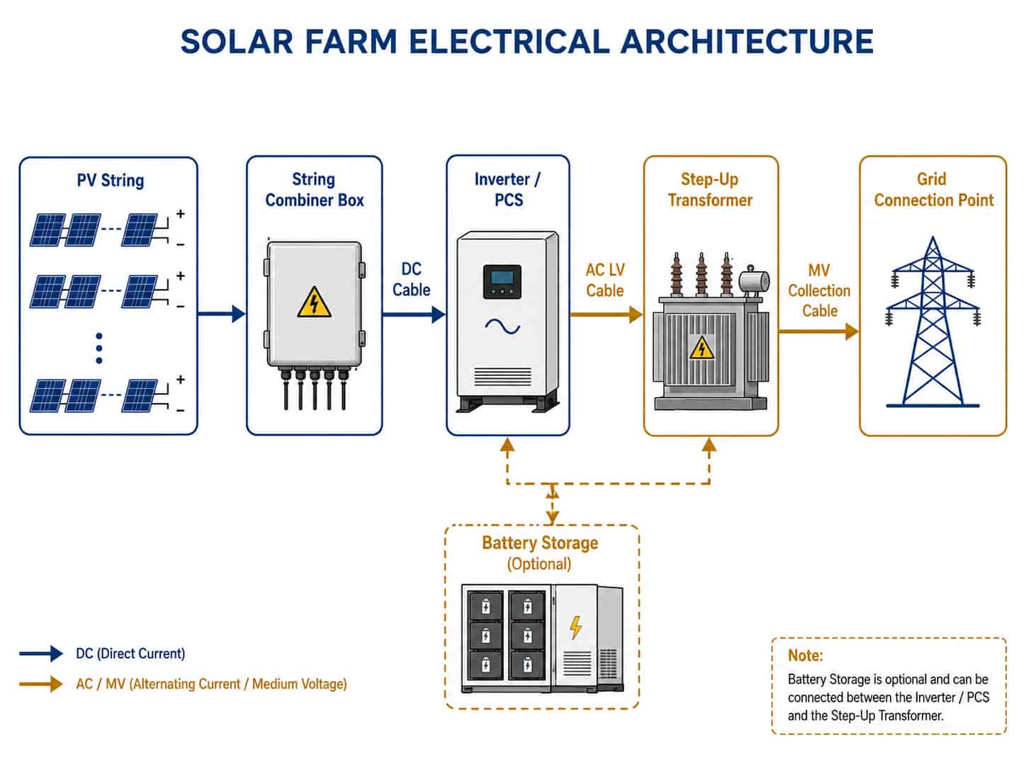
- PV modules generate DC power — individual modules connected in series to form strings, each string producing 600–1500V DC depending on module specifications and inverter input range
- String combiner boxes (SCBs) aggregate multiple PV strings in parallel, providing string-level fusing and a single DC output per combiner
- DC cables carry current from combiner boxes to central inverters, or strings connect directly to string inverters without a combiner
- Inverters convert DC to AC — central inverters for large installations, string inverters for distributed or rooftop-style layouts
- AC LV cables carry inverter output to a pad-mounted or skid-mounted step-up transformer
- Step-up transformers raise voltage from inverter output (typically 315V–690V AC) to medium voltage (6kV, 10kV, 20kV, or 33kV) for collection
- MV AC collection cables run underground from transformer stations across the site to the main substation
- Main substation steps up to transmission voltage for grid injection, or connects directly to a distribution grid point
Each segment of this architecture has distinct cable and equipment specifications. Procurement errors at any stage — undersized DC cables, wrong voltage-rated collection cables, mismatched inverter and transformer specifications — affect system output and project timeline.
Key Point: The DC and AC sides of a solar farm are electrically separate domains with different cable standards, voltage ratings, and safety requirements. DC cables must be rated for DC voltage (not AC — the rating is different), UV-resistant for outdoor exposure, and TÜV or IEC 62930 certified. AC cables follow IEC 60502 as for any power cable installation.
DC Side Cables: String Cable and DC Main Cable
The DC cable system covers two distinct cable types with different specifications and installation conditions.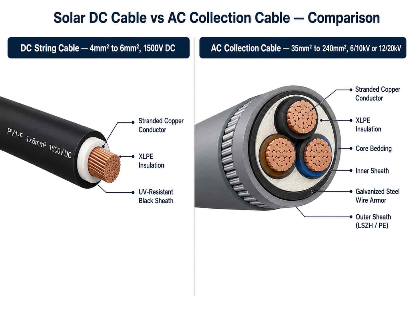
PV String Cable (Module to Combiner Box)
PV string cables connect individual solar modules in series and carry the string current from the last module to the string combiner box. These cables are exposed to direct sunlight, UV radiation, extreme temperature cycling, and in ground-mounted installations, contact with soil or gravel.
Standard specification for PV string cable:
- Voltage rating: 1500V DC (current standard for utility-scale; older systems use 1000V DC)
- Conductor: tinned stranded copper, 4mm² or 6mm² (most common for utility-scale strings)
- Insulation and sheath: XLPE or EVA compound, UV-resistant, halogen-free
- Temperature range: -40°C to +90°C continuous (critical for desert or tropical climates)
- Connector: MC4 or compatible plug-and-socket system at both ends
- Certification: IEC 62930 (international standard for PV cables) or TÜV 2 Pfeil (German certification widely accepted globally)
- Color: red for positive, black for negative (international convention — confirm local code)
Key Point: PV string cable must be rated for DC voltage — not AC. A cable rated 1kV AC is not equivalent to 1kV DC; the DC voltage rating accounts for the absence of zero crossings that limit breakdown in AC systems. Always specify 1500V DC rating for current utility-scale projects.
DC Main Cable (Combiner Box to Inverter)
The DC main cable carries the combined output of multiple strings from the combiner box to the central inverter. This cable carries higher current than string cable and may run longer distances across the site:
- Voltage rating: 1500V DC
- Conductor: stranded copper, cross-section sized for combined string current — typically 50mm² to 240mm² depending on combiner box capacity and cable run length
- Insulation: XLPE, UV-resistant where exposed
- Installation: underground in conduit or direct burial with UV-resistant conduit; overhead in cable tray
- Certification: IEC 62930 for exposed sections; IEC 60502-1 acceptable for fully enclosed/underground runs
Note: For long DC cable runs (above 50–100m depending on current), voltage drop calculation is essential. DC voltage drop directly reduces the operating point of the inverter MPPT and system output. Size conductors to keep DC voltage drop below 1–2% of string voltage under full load.
AC LV Cables: Inverter to Transformer
The AC cables between the inverter output terminals and the step-up transformer LV terminals carry the full inverter AC output. These cables are typically short (under 20m for pad-mount configurations) but carry high current at relatively low voltage:
- Voltage grade: 0.6/1kV (inverter output is typically 315V–690V AC three-phase)
- Conductor: copper, cross-section sized for full inverter rated current
- Core configuration: 3-core or 4-core for three-phase output; single-core in trefoil for large inverters
- Insulation: XLPE or PVC; LSZH where cables pass through enclosed spaces
- Standard: IEC 60502-1
For central inverter installations, the AC LV feeder current can be very high — a 3.15MW central inverter at 630V AC produces approximately 2,900A per phase, requiring very large cross-sections or multiple parallel cables per phase. Confirm the inverter terminal configuration and maximum terminal conductor size before specifying the LV feeder cable.
MV AC Collection Cables
The medium voltage collection cables form the backbone of the solar farm’s AC infrastructure, running underground from each inverter/transformer station to the main substation. These cables carry the highest voltages on site and require the most careful specification.
Key specification parameters for MV collection cables:
- Voltage grade: determined by the collection network voltage — typically 6/10kV, 12/20kV, or 19/33kV depending on project size and grid connection point
- Conductor: copper or aluminum; aluminum increasingly used for large cross-sections (150mm² and above) to reduce cable weight and cost on long runs
- Insulation: XLPE with semi-conductive screens and copper tape or wire metallic screen — mandatory for MV cables
- Armoring: SWA for direct burial; unarmored in duct or tray
- Standard: IEC 60502-2
- Cable sizing: based on peak current from all inverter/transformer stations feeding the cable, with thermal capacity verified for continuous operation
Key Point: MV collection cable sizing must account for both steady-state thermal current capacity and fault current withstand. During a downstream fault, the cable must withstand the fault current until the protection operates. Confirm fault level with the grid connection agreement and verify cable short-circuit capacity with the manufacturer.
Inverter and Transformer Specification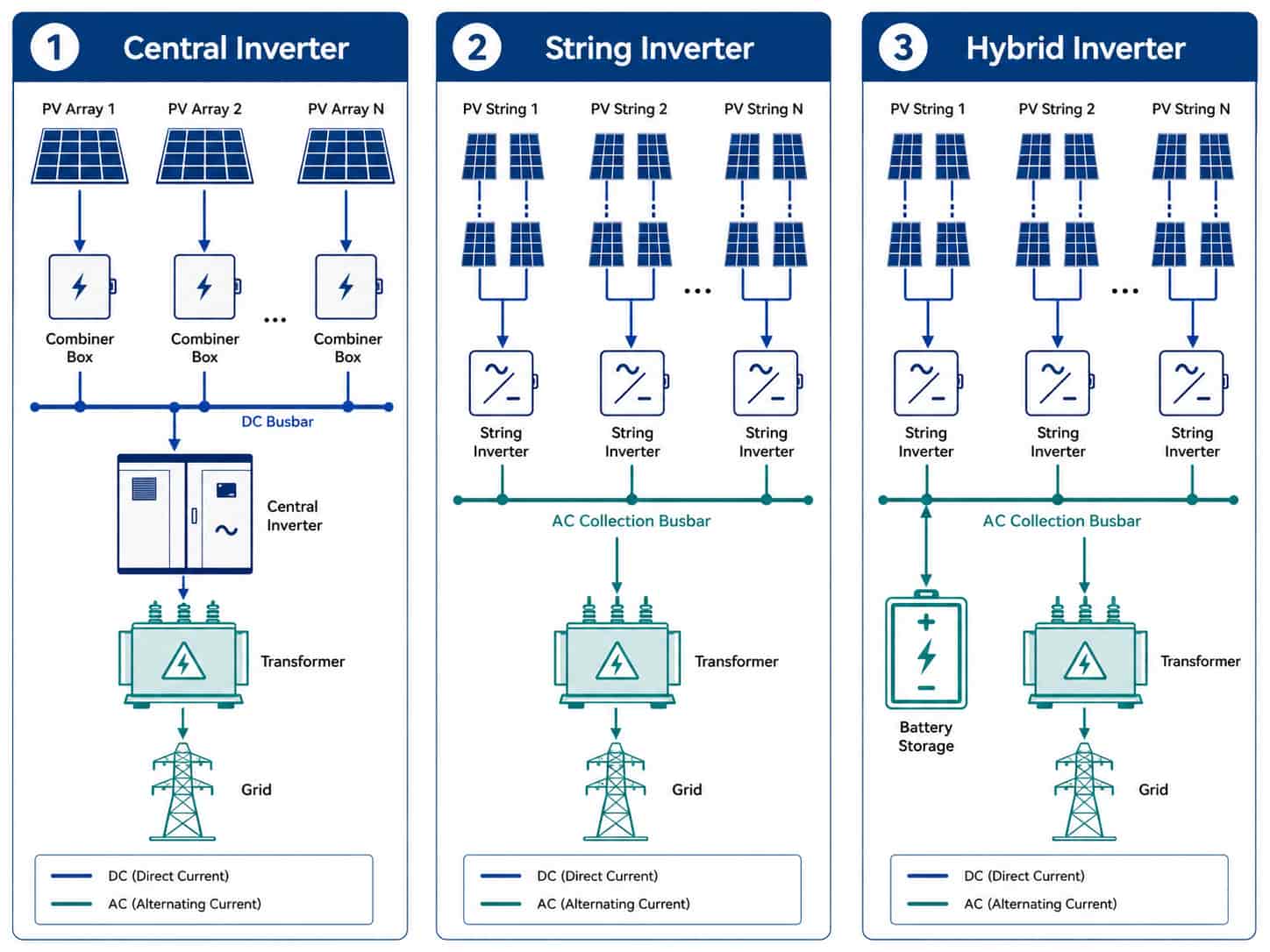
Solar Inverter Types
The choice of inverter topology affects the DC and AC cable configuration, string combiner requirements, and monitoring architecture:
- Central inverter: single large inverter (500kW–5MW+) per inverter station, accepts multiple DC inputs from combiner boxes. Lower per-kW cost, simpler AC wiring, but single point of failure for a large power block
- String inverter: smaller inverters (25kW–110kW) connected directly to one or two PV strings. Higher granularity monitoring, reduced mismatch losses, but more units and more AC cabling to aggregate
- Hybrid inverter: combines solar inverter with battery storage interface — relevant for solar-plus-storage projects where BESS is part of the scope
For utility-scale projects above 10MW, central inverters or high-power string inverters (250kW–350kW) are most commonly specified. For projects below 5MW or with complex terrain and shading, distributed string inverters are preferred for their MPPT flexibility.
Step-Up Transformers
Every inverter station requires a dedicated or shared step-up transformer to raise the inverter AC output to the MV collection voltage. Specification parameters:
- Primary voltage: match inverter AC output voltage (typically 315V, 400V, or 630V — confirm with inverter specification)
- Secondary voltage: match MV collection network voltage (6kV, 10kV, 20kV, or 33kV)
- Rating (kVA): match total connected inverter capacity per transformer, with 10–15% overrating headroom
- Vector group: confirm with grid authority — Dyn11 is most common for solar farm applications
- Type: oil-immersed or dry-type; oil-immersed preferred for outdoor pad-mount; dry-type for indoor or skid-mounted installations
- Protection: integrated HV and LV protection relays, surge arresters on MV terminals
- Standard: IEC 60076
Note: The primary voltage tap setting on the transformer must match the inverter’s actual AC output voltage under operating conditions — not the rated voltage. Inverters may operate at a different point on the voltage range depending on grid conditions. Confirm the operating voltage range with the inverter supplier before finalizing transformer tap changer specification.
String Combiner Boxes and DC Switchgear
String combiner boxes aggregate PV string inputs and provide string-level overcurrent protection. Key specification parameters:
- Number of string inputs: determined by project design — typically 8, 12, 16, or 24 inputs per combiner
- Input fuse rating: sized to string short-circuit current (Isc) — typically 15A or 20A per string
- Output: single DC output with DC disconnect switch or circuit breaker
- Monitoring: string-level current monitoring for performance and fault detection (increasingly standard on utility-scale projects)
- Enclosure: IP65 minimum for outdoor ground-mounted installations; stainless steel or GRP enclosure for coastal or high-humidity environments
- DC voltage rating: 1500V DC for current utility-scale standard
- Standard: IEC 62548 (PV array design) for system-level requirements; IEC 60947 for switchgear components
Earthing System for Solar Farms
The earthing system of a solar farm serves both safety and lightning protection functions. Utility-scale solar farms typically implement:
- Perimeter earth ring: bare copper conductor (typically 95mm² or 120mm²) buried around the site perimeter, connected to the main substation earth terminal
- Equipotential bonding grid: copper conductors connecting all metal structures (panel mounting frames, inverter stations, transformer stations) to the perimeter ring at regular intervals
- Structure earth conductors: green/yellow insulated copper conductor (16mm² or 25mm²) bonding individual panel mounting structures to the grid
- Lightning protection: air termination network on inverter stations and substation, connected via down conductors to dedicated earth pits
- DC system earthing: TN-S or IT earthing for the DC side — confirm with inverter specification and local grid authority requirements
Key Point: For solar farms with BESS (battery energy storage), the earthing system must accommodate both the PV DC system and the battery DC system, which may have different earthing requirements. Confirm with the battery and inverter suppliers before the earthing design is finalized.
Balance of Plant: Auxiliary Power and Monitoring
Beyond the main power circuits, a solar farm requires a balance-of-plant electrical package covering:
Auxiliary Power Supply
- LV distribution board for site auxiliary loads: inverter cooling, lighting, CCTV, communications, access control
- Auxiliary transformer: small kVA transformer stepped down from MV collection network or dedicated grid connection for site supply
- UPS for critical monitoring and protection systems: SCADA, protection relays, communications equipment
- Cable: standard LV power cable and control cable to IEC 60502-1 and IEC 60227
SCADA and Monitoring
- Fiber optic backbone cable: OS2 single-mode fiber for SCADA communication between inverter stations and main substation control room
- Cat6A or Cat5e cable for local inverter Ethernet monitoring ports
- RS485 shielded twisted pair for Modbus-based monitoring where fiber is not used
- Weather station cabling: irradiance sensor, temperature sensor, and wind sensor signal cables to SCADA panel
Security and Site Infrastructure
- CCTV: IP cameras on perimeter fence and inverter stations; fiber or Cat6 cable runs
- Access control: card readers at site entry and inverter station doors
- Perimeter lighting: IEC 60598 luminaires on posts around site boundary, wired from auxiliary distribution