Medium voltage cable joints and terminations are among the most overlooked items in B2B cable procurement. Buyers focus on specifying the cable correctly — voltage grade, conductor cross-section, insulation type, armoring — but frequently omit or underspecify the accessories required to terminate and joint the cable. Yet cable accessories are the most failure-prone element of any MV cable system: the cable itself, correctly manufactured and installed, may last 40 years; a poorly selected or incorrectly installed termination can fail within months.
This guide covers the types of MV cable accessories available, the critical parameters that determine compatibility, the differences between cold shrink and heat shrink technology, indoor and outdoor selection criteria, and what to specify in a B2B procurement inquiry to ensure accessories arrive that are compatible with the cable being supplied.
Why MV Cable Accessories Are Critical to System Reliability
A medium voltage cable joint or termination must do the same job as the cable itself — control the electric field at the point where the cable’s geometric symmetry is disturbed. In a continuous MV cable run, the conductor screen, insulation, and metallic screen maintain a uniform radial electric field. At the end of the cable (termination) or where two cable lengths are joined (joint), this uniform geometry is interrupted — the screens are cut back, the conductor is exposed, and the electric field concentrates at the screen cut points.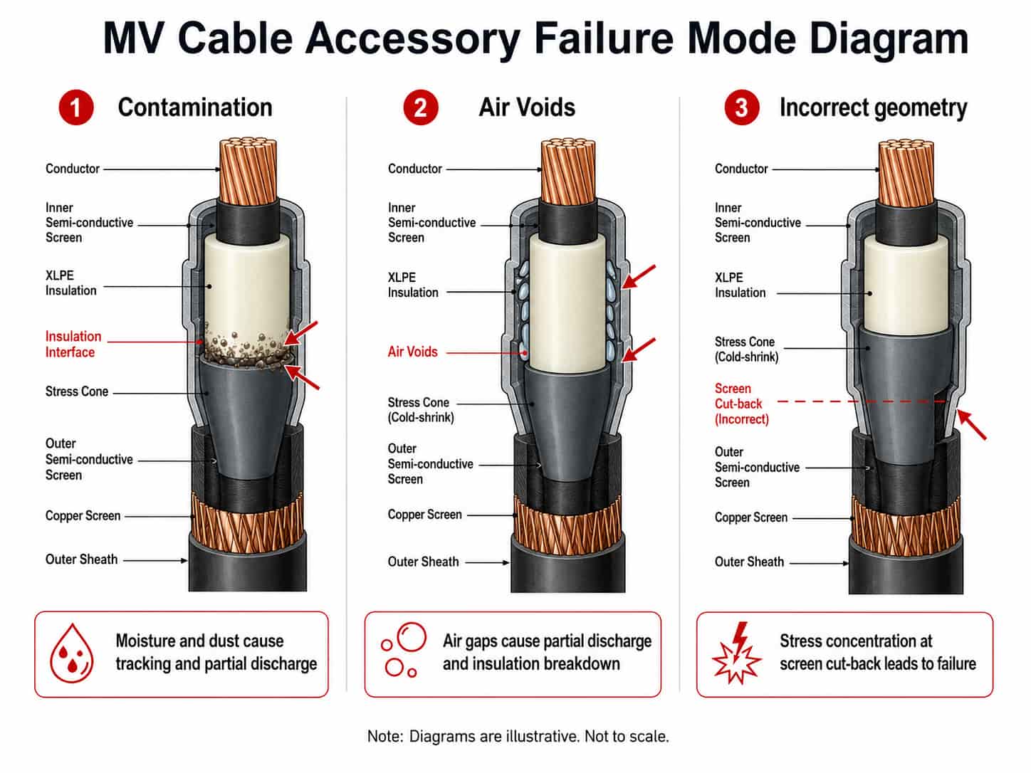
This electric field concentration is the fundamental technical challenge of MV cable accessories. If it is not managed — by a properly designed and installed stress control element — partial discharge occurs at the screen cut-back, progressive insulation degradation follows, and eventually the cable fails in service. The failure mode is not immediate but cumulative: a marginal termination may operate for months before the accumulated partial discharge damage causes a fault.
The three most common causes of MV cable accessory failure are:
- Contamination: moisture, dust, or conductor compound residue at the cable insulation surface during installation — prevents the cold shrink or heat shrink material from forming a complete interface seal
- Air voids: inadequate radial pressure between the accessory body and the cable insulation, leaving air pockets that sustain partial discharge
- Incorrect geometry: stress cone positioned at the wrong distance from the screen cut point, or cable dimensions outside the accessory’s design range
Key Point: Cable accessories are not generic — they are designed and tested for specific cable outer diameter ranges, screen cut-back dimensions, and voltage grades. A termination kit specified for a 6/10kV cable with an outer insulation diameter of 18–22mm will not perform correctly on a 6/10kV cable with an outer insulation diameter of 24mm, even though both cables are nominally the same voltage grade. Always confirm the cable’s measured outer insulation diameter and screen outer diameter with the accessory manufacturer before ordering.
Types of MV Cable Accessories
Terminations
A cable termination is the assembly at the end of a cable that provides a safe, insulated, weatherproof (where required) connection point between the cable and the connected equipment — switchgear, transformer terminals, ring main units, or cable boxes.
MV terminations consist of:
- Stress cone (or stress control element): manages the electric field concentration at the screen cut-back point — the most technically critical component
- Insulating body: cold-shrink tube, heat-shrink tube, or pre-moulded rubber boot — provides insulation and environmental sealing over the prepared cable end
- Conductor connector or lug: compression or mechanical connector joining the cable conductor to the equipment terminal
- Outer seal: seals the termination body to the cable outer sheath to prevent moisture ingress
- Screen bonding braid or wire: provides the earth connection from the cable metallic screen to the equipment earth terminal
Straight Joints (Inline Joints)
A straight joint connects two lengths of the same cable type and cross-section in a continuous run. The joint must restore the electrical properties of the continuous cable — conductor connection, conductor screen continuity, insulation, insulation screen continuity, metallic screen continuity, armoring continuity, and outer sheath.
Straight joints are used when:
- The cable route length exceeds the maximum drum length — underground distribution runs longer than 500m typically require one or more straight joints
- A cable is damaged in service and a section requires replacement — the replacement section is joined to the existing cable at both ends
- A project cable schedule requires drum lengths shorter than the route length for site logistics reasons
Note: MV straight joints are technically demanding to install — they require precise cable preparation dimensions, clean working conditions, and trained installers. A poorly installed straight joint is the most common cause of MV cable system failure in service. For projects with a significant number of straight joints, confirm that the cable installation contractor has trained and certified jointers for the specific accessory system being used.
Transition Joints
A transition joint connects two cables of different types — most commonly a copper-conductor cable to an aluminum-conductor cable, or an XLPE-insulated cable to a paper-insulated lead-covered (PILC) cable on existing infrastructure. Transition joints require bi-metallic connectors where conductor materials differ and are more complex than straight joints. For new projects where all cable is the same type, transition joints are rarely required.
Cable Sealing Ends (for PILC cable)
Sealing ends are used on paper-insulated lead-covered (PILC) cables — older cable technology still found on existing infrastructure in some markets. For new installation projects using XLPE cable, sealing ends are not required. If connecting new XLPE cable to existing PILC cable, a transition joint is required; the PILC end of the route may also require a new sealing end at the switchgear connection point.
Cold Shrink vs Heat Shrink Terminations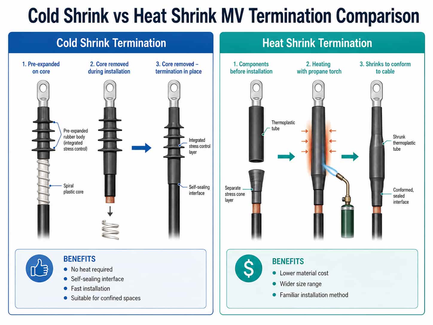
MV cable terminations and joints are available in two primary installation technologies — cold shrink and heat shrink. Both are effective when correctly specified and installed, but have different characteristics that make each preferable in specific situations.
Cold Shrink Technology
Cold shrink accessories use pre-expanded rubber tubes (typically silicone or EPDM rubber) supported by a removable internal plastic spiral core. During installation, the plastic core is removed and the rubber tube contracts onto the cable by its own elastic recovery — no heat source is required.
Advantages of cold shrink:
- No heat required: can be installed in confined spaces, near flammable atmospheres, or where open flame is prohibited (oil and gas, mines, chemical plants)
- Consistent radial pressure: the elastic recovery of the rubber provides consistent and sustained radial pressure on the cable insulation — minimizing air voids at the interface
- Self-sealing: the rubber-to-XLPE interface provides a water-tight seal without additional sealant in most applications
- Fast installation: trained jointers can complete a cold-shrink termination in 30–45 minutes once the cable is prepared
- Wide temperature range: suitable for arctic installations without special precautions — cold shrink rubber remains flexible at low temperatures
Disadvantages:
- Higher material cost than heat shrink
- Pre-expanded units have a defined shelf life — check the expiry date on delivery
- The pre-expanded tube must be stored uncompressed — do not allow the plastic spiral core to be removed until installation
Heat Shrink Technology
Heat shrink accessories use thermoplastic or cross-linked polyolefin tubes and components that shrink to conform to the cable when heated with a propane torch or industrial heat gun.
Advantages of heat shrink:
- Lower material cost than cold shrink for equivalent voltage rating
- Available in a very wide range of sizes — particularly useful for non-standard cable dimensions
- No shelf life concern for unexpanded components
- Suitable for outdoor installation where a weatherproof mastic sealant is applied at the same time as shrinking
Disadvantages:
- Open flame hazard: not suitable where hot work is prohibited
- Installation quality more variable: excessive or insufficient heat affects shrinkage uniformity and adhesive activation
- Requires controlled heating technique to avoid under-shrinking or burning the material
- In cold climates, pre-warming the cable and components before installation is necessary
Key Point: For most B2B project procurement, cold shrink is the preferred technology for MV cable terminations and joints — it produces more consistent results with less installer skill variability and is suitable in a wider range of installation environments. Specify cold shrink unless the project engineer has a specific reason to require heat shrink (typically cost reduction on large volume projects where skilled jointers are available).
Indoor vs Outdoor Terminations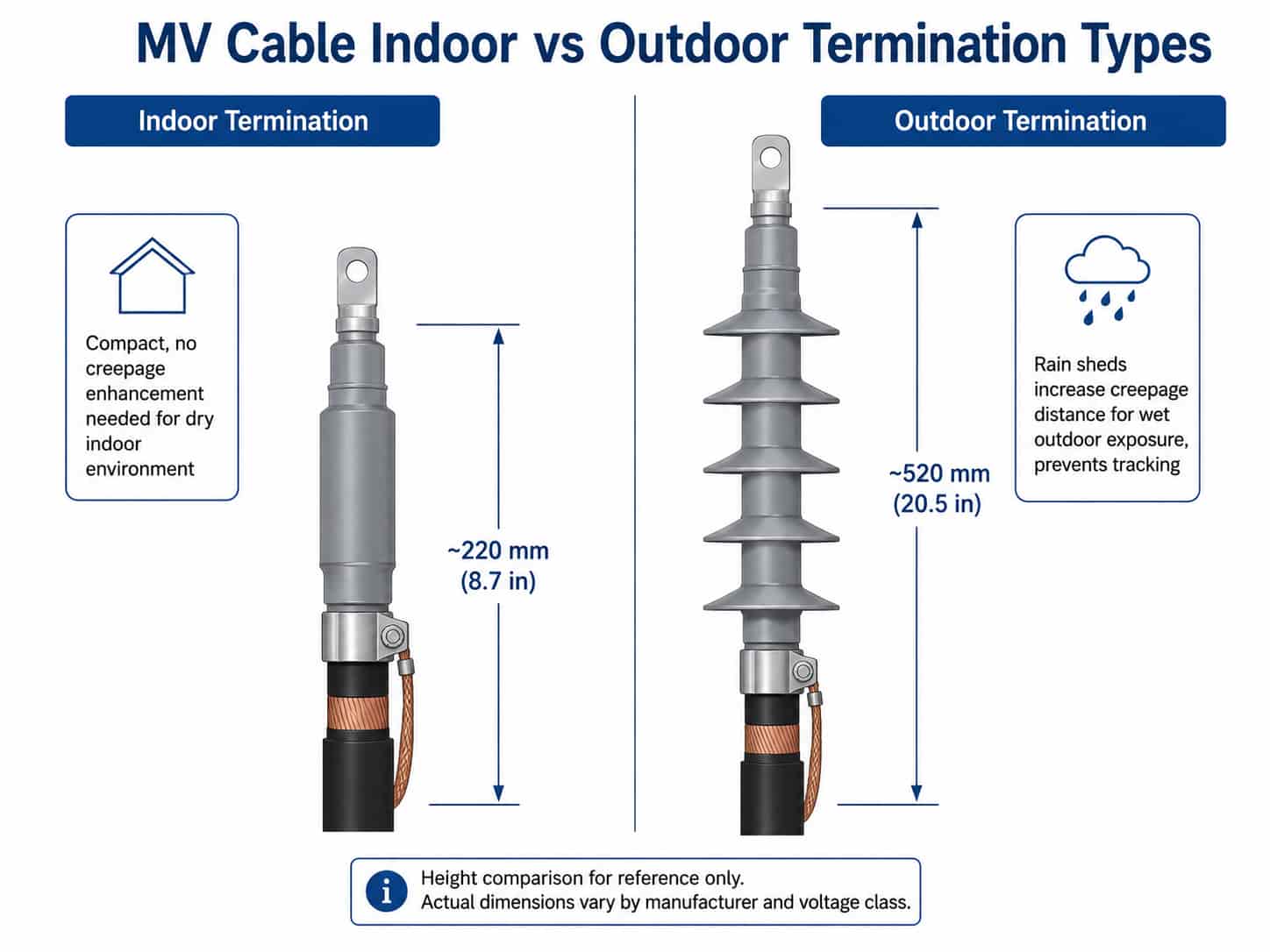
MV cable terminations are classified as indoor or outdoor based on the installation environment. The key difference is creepage distance — the surface path length along the insulating body from the live conductor to the earthed end of the termination. In outdoor environments, rain, pollution, and condensation on the termination surface create a conductive film that can initiate surface tracking if the creepage distance is insufficient.
Indoor Terminations
Indoor terminations are designed for installation inside switchgear cubicles, cable boxes, transformer terminals, and other enclosed equipment where the termination is not exposed to rain, condensation, or industrial pollution. They are compact, typically shorter than outdoor equivalents, and do not require rain sheds or skirts.
- Typical installation: inside switchgear, ring main units, transformer cable boxes, indoor substations
- Pollution level: none — protected from weather
- Creepage distance: per IEC 60815 Pollution Level I (clean, indoor)
- Construction: compact body without rain sheds
Outdoor Terminations
Outdoor terminations are designed for direct exposure to weather — rain, UV radiation, pollution, and condensation. They have an extended body with rain sheds (also called skirts or petticoats) that increase the creepage distance and prevent water bridging the full termination surface.
- Typical installation: outdoor switchgear, overhead line connections, outdoor transformer terminals, substations without weather protection
- Pollution level: IEC 60815 Pollution Level II to IV depending on the industrial environment
- Creepage distance: increased versus indoor — longer body with multiple rain shed skirts
- Material: silicone rubber outdoor terminations are increasingly preferred over porcelain for their resistance to vandalism, light weight, and self-cleaning properties
Key Point: Never install an indoor termination in an outdoor or exposed location — even under a weatherproof cover that you think provides adequate protection. The creepage distance of an indoor termination is insufficient for wet outdoor conditions. Tracking failures on incorrectly specified indoor-rated terminations in outdoor applications are common and typically result in a phase-to-earth fault with significant equipment damage.
Critical Selection Parameters: What You Must Confirm Before Ordering
MV cable accessories are highly specific to the cable they are installed on. The following parameters must be confirmed — measured, not assumed — before placing an order for cable accessories:
For B2B procurement from Chinese manufacturers, confirm that accessory suppliers hold type test reports from an accredited laboratory for the specific accessory construction and voltage grade. Generic product declarations without type test reports are not adequate for project compliance in most markets.
Note: The cable and the cable accessory do not have to come from the same manufacturer, but they must be confirmed compatible. The accessory manufacturer must confirm in writing that the product is suitable for the specific cable construction — voltage grade, outer insulation diameter range, screen outer diameter, and armor type. Some project specifications require a system type test (cable + accessory tested together) — confirm whether this is a requirement before specifying accessories from a different supplier than the cable.
Practical Procurement Advice: Accessories and Cable Together
The most effective approach for B2B procurement of MV cables with accessories is to specify and procure them together — ideally from the same supplier, or with confirmed compatibility confirmed in writing before ordering. The following practical steps prevent the most common accessory procurement errors:
- Order cable accessories after confirming the cable’s actual measured dimensions — not from the nominal cable specification
- Confirm the accessory voltage grade matches the cable voltage grade exactly — a 6/10kV cable requires a 6/10kV accessory kit, not a 12/20kV kit (oversized) or a 3.6/6kV kit (undersized)
- Specify the number of cores — a 3-core cable needs a 3-core straight joint kit; three single-core terminations are required for a 3-core cable at each end (one per phase)
- Confirm indoor vs outdoor for every termination — specify individually for each installation point, not generically for the project
- Include the screen bonding arrangement in the specification — solid bonding (both ends earthed) or single-point bonding (one end earthed) for single-core cables affects the accessory configuration
- For armored cables, specify whether an armoring continuity connector is required in straight joints — some armoring continuity kits are sold separately from the joint body kit
- Order 10–15% spare accessories for a project — straight joints are sometimes damaged during installation and require replacement; having spare kits avoids project delays
Procurement Checklist for MV Cable Accessories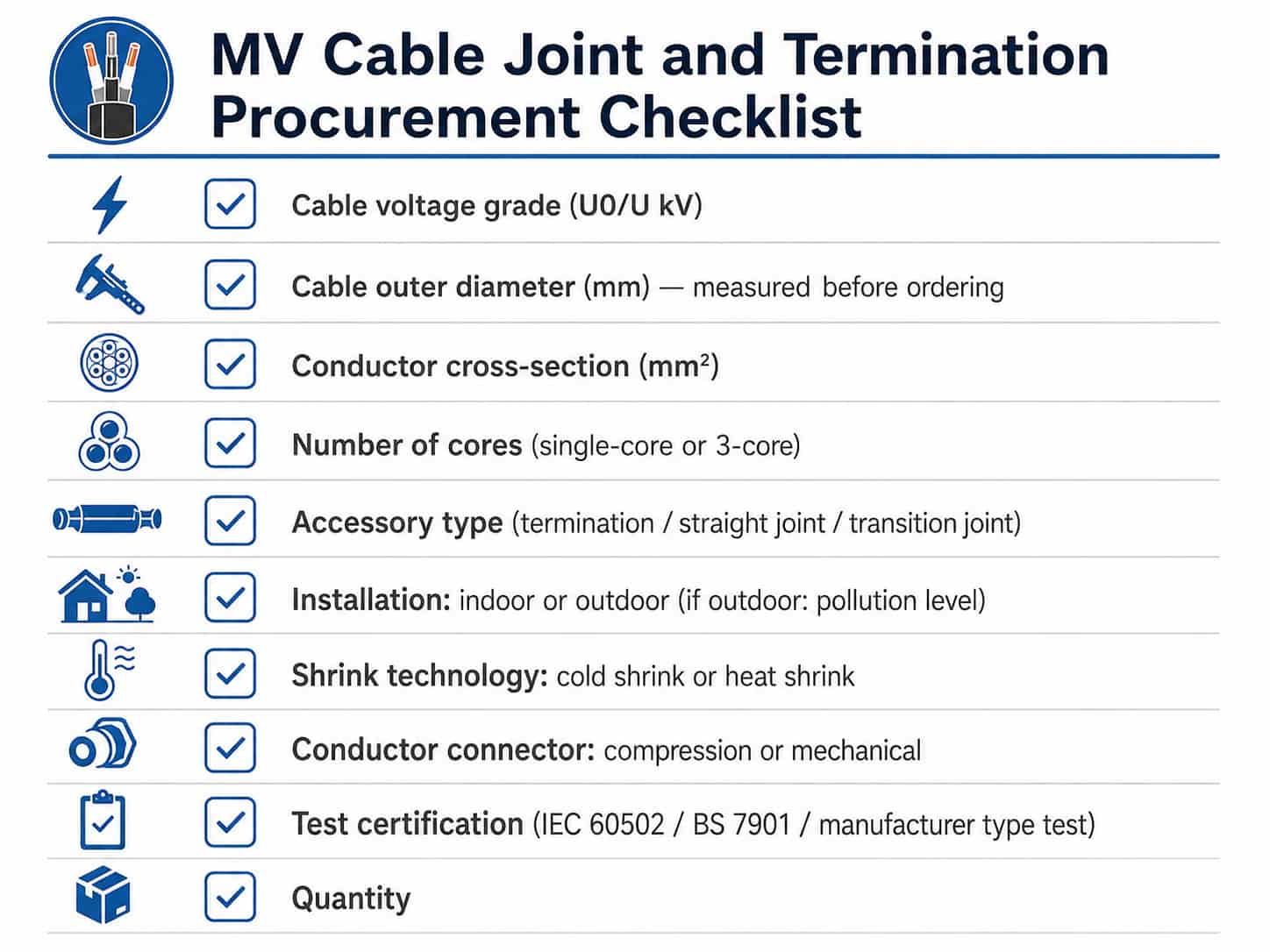
When preparing an accessory inquiry to accompany an MV cable order, provide the following:
- Cable voltage grade (U0/U format): e.g. 6/10kV, 12/20kV, 19/33kV
- Cable outer insulation diameter (mm): measured or confirmed from cable datasheet
- Metallic screen outer diameter (mm): from cable datasheet
- Conductor material: copper (CU) or aluminum (AL)
- Conductor cross-section (mm²)
- Number of cores: single-core or 3-core
- Accessory type: termination (indoor or outdoor) or straight joint
- Shrink technology preference: cold shrink or heat shrink
- Quantity: number of termination kits and/or joint kits
- Applicable standard: IEC 60502-4, BS 7901, or project specification
- Screen bonding arrangement: solid bonding or single-point bonding (for single-core cables)
- Armoring type: SWA or AWA — confirm if armoring continuity kit is required in joints
Quotation Requirements
RichingPower supplies MV power cables and can source compatible MV cable accessory kits — cold shrink terminations, heat shrink terminations, and straight joints — from accredited manufacturers. To receive an accurate quotation for cable accessories alongside your cable order, please provide:
- Cable voltage grade, conductor cross-section, and number of cores
- Cable outer insulation diameter (from cable datasheet or measured on delivery)
- Accessory type required: termination (indoor or outdoor) and/or straight joint
- Quantity of each accessory type
- Shrink technology preference: cold shrink or heat shrink
- Applicable standard and any type test requirements
Submit your MV cable and accessory specification via the RichingPower contact page. For projects with a cable schedule, attaching the schedule allows us to identify the accessory requirements for each cable section and provide a comprehensive itemized quotation for cables and accessories together.
Conclusion
MV cable joints and terminations are not an afterthought — they are integral to the electrical performance and long-term reliability of the cable system. Procuring the wrong accessory for the cable installed, or specifying an indoor termination for an outdoor location, creates failure modes that the cable itself could never cause. The accessory selection parameters — voltage grade, cable insulation diameter, indoor/outdoor, cold shrink or heat shrink — must be confirmed against the actual cable delivered, not the nominal specification.
For B2B project buyers, the most effective approach is to specify cable accessories at the same time as the cable, confirm compatibility between the cable and accessory dimensions in writing, and include accessories in the project cable schedule alongside the cable quantities. This prevents the common situation of cable arriving on site with no compatible accessories available to complete the installation.
For guidance on MV cable construction and voltage grade selection, see Low Voltage vs Medium Voltage Cable: A Procurement Guide. For armoring selection which affects joint kits, see
Armored vs Unarmored Cable: When to Specify SWA. Contact RichingPower with your cable schedule for a combined cable and accessories quotation.