Industrial manufacturing plants represent one of the most demanding and varied electrical procurement environments in B2B project supply. A greenfield factory project requires a complete electrical package spanning medium voltage supply infrastructure, step-down transformers, low voltage main distribution, motor control centers, branch circuit wiring, control and instrumentation cabling, and plant-wide earthing — all coordinated with the mechanical process design.
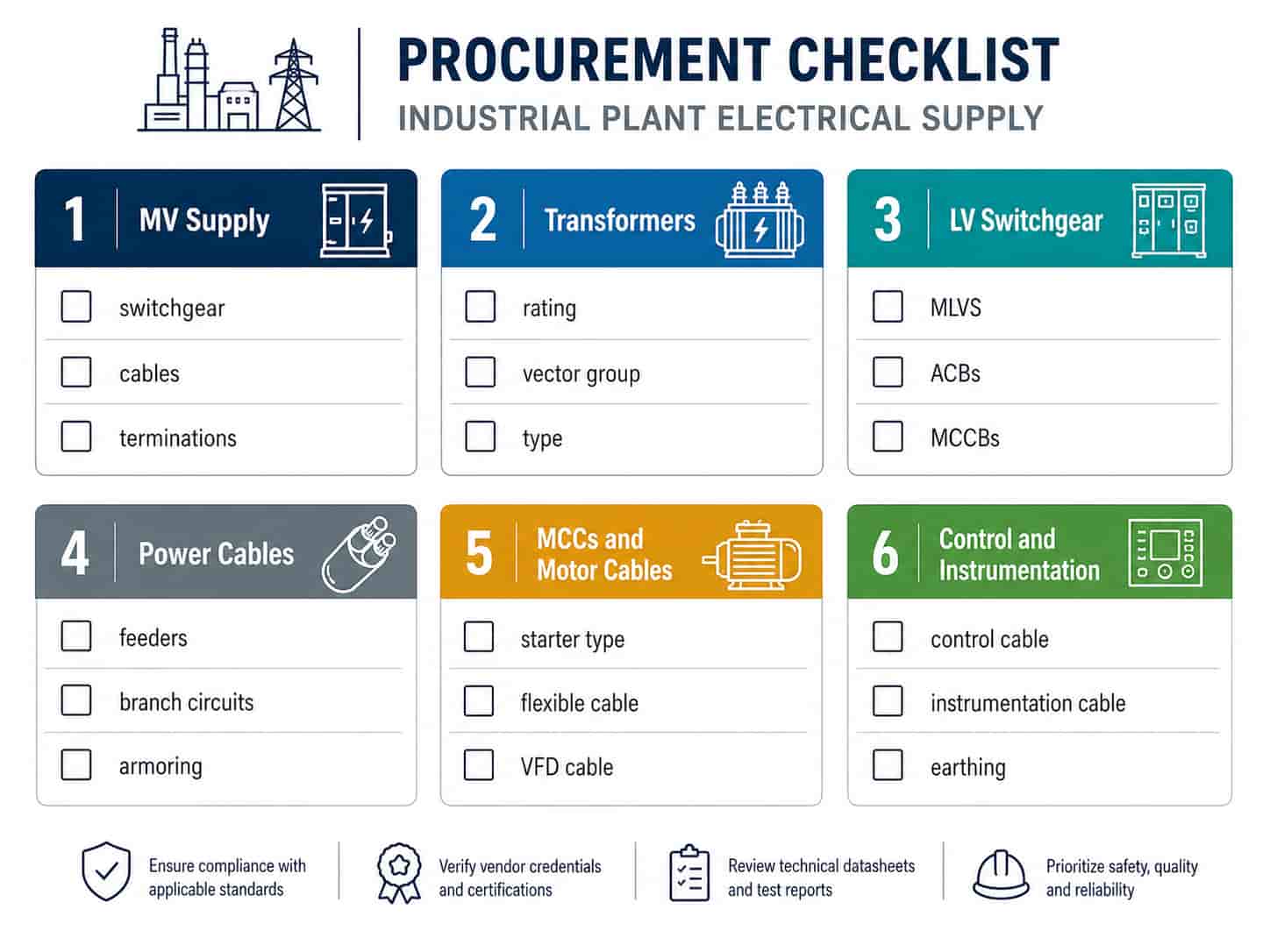
This guide covers the major electrical procurement categories for an industrial plant or manufacturing facility project. It is structured for EPC contractors, plant electrical engineers, and procurement teams sourcing electrical products from China, and covers specification requirements, product selection criteria, and the questions to confirm before placing orders.
Industrial Plant Power Distribution Architecture
The power distribution hierarchy in an industrial plant follows a standard structure from the utility connection point to individual loads. Understanding this hierarchy is the starting point for organizing the procurement package by voltage level and system function.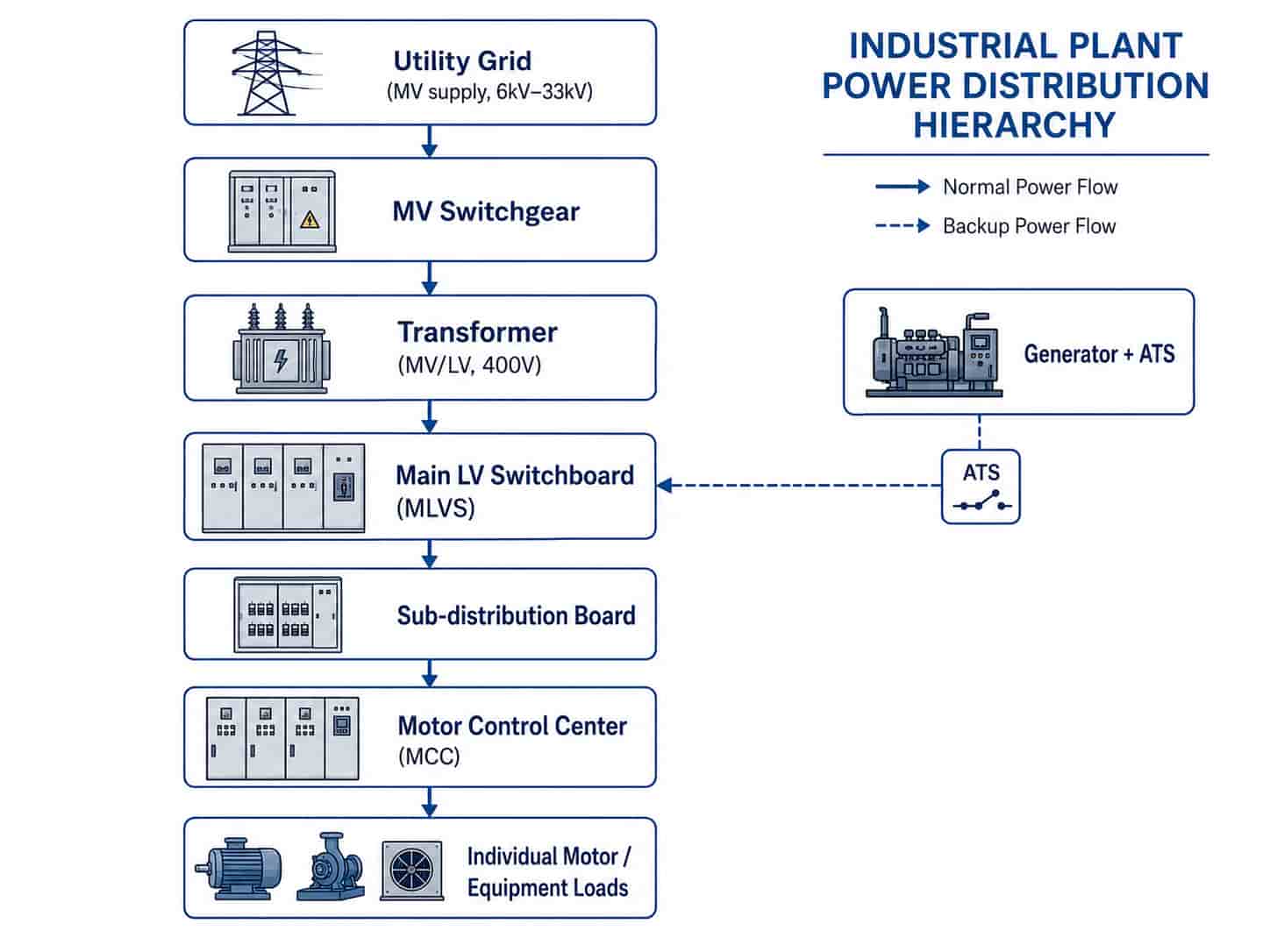
- Utility medium voltage supply: incoming power at 6kV, 10kV, 20kV, or 33kV from the grid — voltage determined by plant load and local utility
- MV switchgear: ring main unit (RMU) or primary switchboard receiving the utility connection and distributing to on-site transformers
- MV/LV transformer: steps down from utility voltage to 400V (or 690V for large motor drives) for plant distribution
- Main LV switchboard (MLVS): the primary LV distribution point, distributing to sub-boards, MCCs, and large individual loads
- Sub-distribution boards: secondary distribution panels serving defined areas or process zones within the plant
- Motor control centers (MCCs): dedicated panels housing motor starters, soft starters, and VFDs for process machinery
- Branch circuit wiring: individual cable runs from distribution boards and MCCs to motors, lighting, HVAC, and process equipment
- Control and instrumentation wiring: low-voltage control cables for PLC I/O, relay logic, and 4–20mA instrumentation loops
For larger industrial plants (above 5MW total connected load), a secondary MV distribution ring is sometimes used to feed multiple transformer substations across the site, reducing LV cable runs and improving power quality at distant loads.
Key Point: The transformer secondary voltage selection — 400V or 690V — significantly affects the procurement package. A 690V distribution system reduces current for the same power, allowing smaller cable cross-sections and lower I²R losses over long plant runs. However, it requires 690V-rated MCCs, motor starters, and cables throughout the LV system. Confirm the distribution voltage with the electrical design engineer before specifying any LV equipment or cables.
MV Supply Infrastructure
The medium voltage supply infrastructure is the first procurement category and determines the entry point for all downstream systems.
MV Switchgear
The MV switchgear at the plant entry point receives the utility supply and provides protection, metering, and distribution to transformers. For industrial plants:
- Ring main unit (RMU): compact switchgear for sites with a single transformer connection — load break switch with cable and transformer protection fuse or circuit breaker
- Primary switchboard: for sites with multiple transformer connections or complex MV distribution — includes bus section and multiple outgoing feeder circuits with protection relays
- Insulation medium: SF6-insulated (compact, widely available) or solid dielectric (emerging preference for environmental reasons)
- Protection: overcurrent and earth fault protection relays on outgoing transformer feeders; bus protection for larger switchboards
- Standard: IEC 62271-200 (factory-built MV switchgear), IEC 62271-100 (circuit breakers)
MV Supply Cables
The MV underground cables from the utility connection point to the plant substation:
- Voltage grade: match utility supply voltage — 6/10kV, 12/20kV, or 19/33kV
- Conductor: copper or aluminum, sized for plant maximum demand with derating for installation method
- Construction: XLPE insulation with metallic screen, SWA armoring for direct burial
- Standard: IEC 60502-2
- Terminations: cold-shrink or heat-shrink MV cable termination kits — confirm kit compatibility with cable outer diameter before ordering
For a detailed breakdown of MV cable construction and voltage grade designation, see Low Voltage vs Medium Voltage Cable: A Procurement Guide.
Transformers for Industrial Plants
Industrial plants typically use one or more dedicated MV/LV transformers to supply the LV distribution system. Key specification parameters:
- Rating (kVA): sized for plant maximum demand plus 20–25% growth headroom — common ratings are 630kVA, 1000kVA, 1250kVA, 1600kVA, and 2000kVA per unit
- Primary voltage: match utility MV supply voltage with appropriate tap changer positions (typically ±2×2.5%)
- Secondary voltage: 400V (standard for most industrial LV distribution) or 690V for high-power drive applications
- Vector group: Dyn11 standard for industrial LV distribution — provides neutral for single-phase loads and limits triplen harmonic propagation
- Type: oil-immersed (ONAN) for outdoor substations; dry-type (AN) for indoor installation where oil is not permitted
- Losses: specify maximum no-load and load losses for energy efficiency compliance — EU Tier 2 (EcoDesign) or equivalent
- Standard: IEC 60076
Note: For plants with significant non-linear loads — VFDs, UPS systems, arc furnaces — specify a transformer with a K-factor rating or low-impedance design to handle harmonic currents. Standard distribution transformers may overheat with high harmonic content. Confirm total harmonic distortion (THD) levels with the process electrical engineer before specifying the transformer.
LV Switchgear and Distribution Boards
The main LV switchboard and distribution boards form the backbone of the plant’s LV power system.
Main LV Switchboard (MLVS)
- Busbar rating: sized for transformer full-load current plus diversity factor — typically 1600A to 6300A for industrial plants
- Incoming protection: ACB (air circuit breaker) with adjustable overcurrent and earth fault protection, rated for transformer prospective fault level
- Outgoing circuits: MCCBs for sub-distribution boards; ACBs for MCC incomers and large motor direct feeders
- Busbar material: copper busbar standard; aluminum busbar acceptable for cost reduction on large ratings
- Form of separation: Form 4 Type 7 fully compartmentalized for maintainability in operating plants
- IP rating: IP31 for indoor switchrooms; IP54 for switchgear located in plant areas with dust or splash exposure
- Standard: IEC 61439-1/2
Sub-Distribution Boards
- Rated current to match zone or area load with 20% spare capacity
- MCCB or MCB protection on all outgoing circuits
- Surge protection device (SPD) where boards are located in outdoor or exposed locations
- Neutral and earth busbars sized for system earthing arrangement (TN-S standard for industrial plants)
Key Point: For industrial plants, specify Form 4 separation in the main switchboard even if it increases cost. Form 4 allows individual outgoing circuit MCCBs to be serviced without de-energizing the entire board — critical for plants where production continuity is a priority.
Cable Selection for Industrial Environments
Industrial plants require a wider range of cable types than standard commercial projects, covering power distribution, motor connections, control wiring, and instrumentation.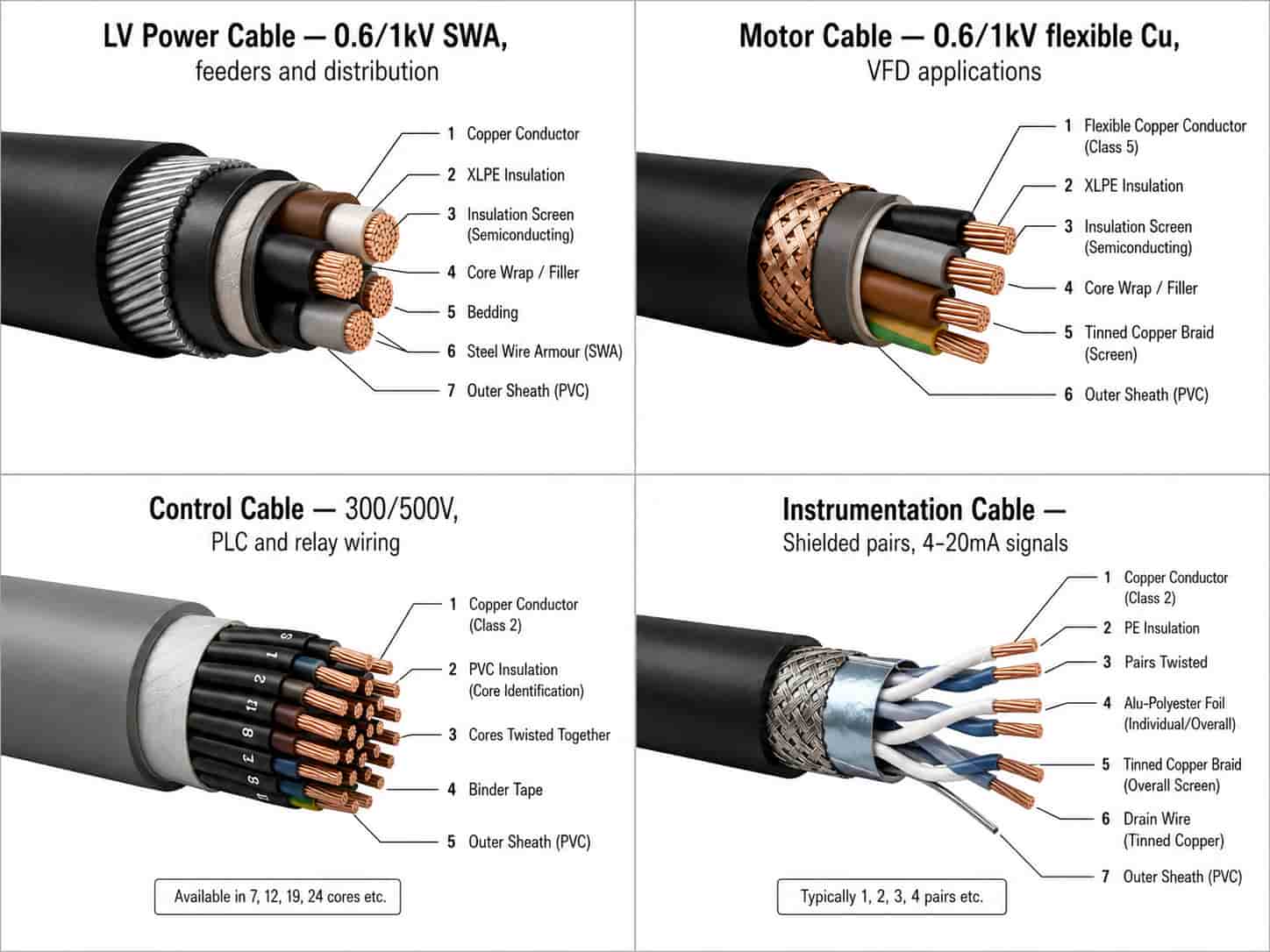
Power Distribution Cables
LV power cables for main feeders, sub-distribution, and branch circuits in industrial plants:
- Voltage grade: 0.6/1kV for all LV distribution
- Conductor: copper preferred for most industrial applications; aluminum for large feeders (185mm²+)
- Insulation: XLPE standard for industrial environments — higher temperature rating than PVC
- Armoring: SWA for cables routed in floor ducts, buried under plant floor, or in areas with mechanical damage risk; unarmored on cable tray
- Standard: IEC 60502-1
Motor Feeder Cables
Motor feeder cables connect motor control center outputs to individual motors. Specification considerations:
- Voltage grade: 0.6/1kV standard; 0.6/1kV rated to 1000V for 690V systems
- Core count: 4-core (3 phases + earth) for standard motors; 5-core for motors with thermistor or brake wiring combined
- Conductor: copper, cross-section sized for motor full-load current with derating for installation conditions
- Flexibility: semi-flexible or flexible construction for motors with vibration or where final connection requires flexibility
- Shielding: unscreened for standard motor connections; screened required for VFD (variable frequency drive) applications — see below
VFD Cable (Variable Frequency Drive Cable)
Cables between VFDs and motors require specialist specification to manage the high-frequency switching noise generated by the drive:
- Symmetrical shielding: full copper braid or foil shield with drain wire, covering all three phases and earth symmetrically
- Low capacitance: minimizes charging current on long cable runs
- Voltage grade: rated for VFD output voltage including transient overvoltage — typically 0.6/1kV minimum, 1.8/3kV for long runs
- Attenuation: shield attenuation rating to limit radiated EMI affecting adjacent instrumentation
- Standard: IEC 60502-1 base; check VFD manufacturer cable specification requirements — some specify minimum shield coverage and attenuation
Key Point: Using standard unscreened motor cable on VFD outputs causes significant electromagnetic interference (EMI) that can disrupt PLC communications, instrumentation signals, and nearby equipment. Always specify dedicated VFD cable — with symmetrical copper braid shield — for any VFD-to-motor connection. Confirm the maximum cable length with the VFD manufacturer for the selected output frequency and voltage.
Control Cable
Control cables carry PLC I/O signals, relay logic wiring, and auxiliary control circuits at 24V DC or 230V AC:
- Voltage rating: 300/500V (standard for control cable)
- Core count: 7, 12, 19, or 27 cores depending on circuit grouping
- Conductor: 1.5mm² or 2.5mm² stranded copper (1.5mm² for digital I/O; 2.5mm² for power control circuits)
- Shielding: overall braid or foil shield for cables near VFDs or in electrically noisy environments
- Standard: IEC 60228 conductors; IEC 60227 or IEC 60502-1 insulation
Instrumentation Cable
Instrumentation cables carry 4–20mA analogue signals, thermocouple signals, and low-level sensor outputs:
- Voltage rating: 300V (instrumentation cable) or 150V (for individual pairs in multi-pair cables)
- Construction: individually screened pairs (IS) for analogue signals; overall screen for digital signal cables
- Conductor: 0.5mm² or 0.75mm² stranded copper — small cross-section as signal cables carry negligible current
- Shielding: individual pair screen plus overall braid or foil shield — critical for noise rejection on long analogue signal runs
- Drain wire: connected at one end only (at the control panel) to prevent earth loops
- Standard: IEC 60228 conductors; manufacturer specification for overall construction
Motor Control Centers and Motor Feeders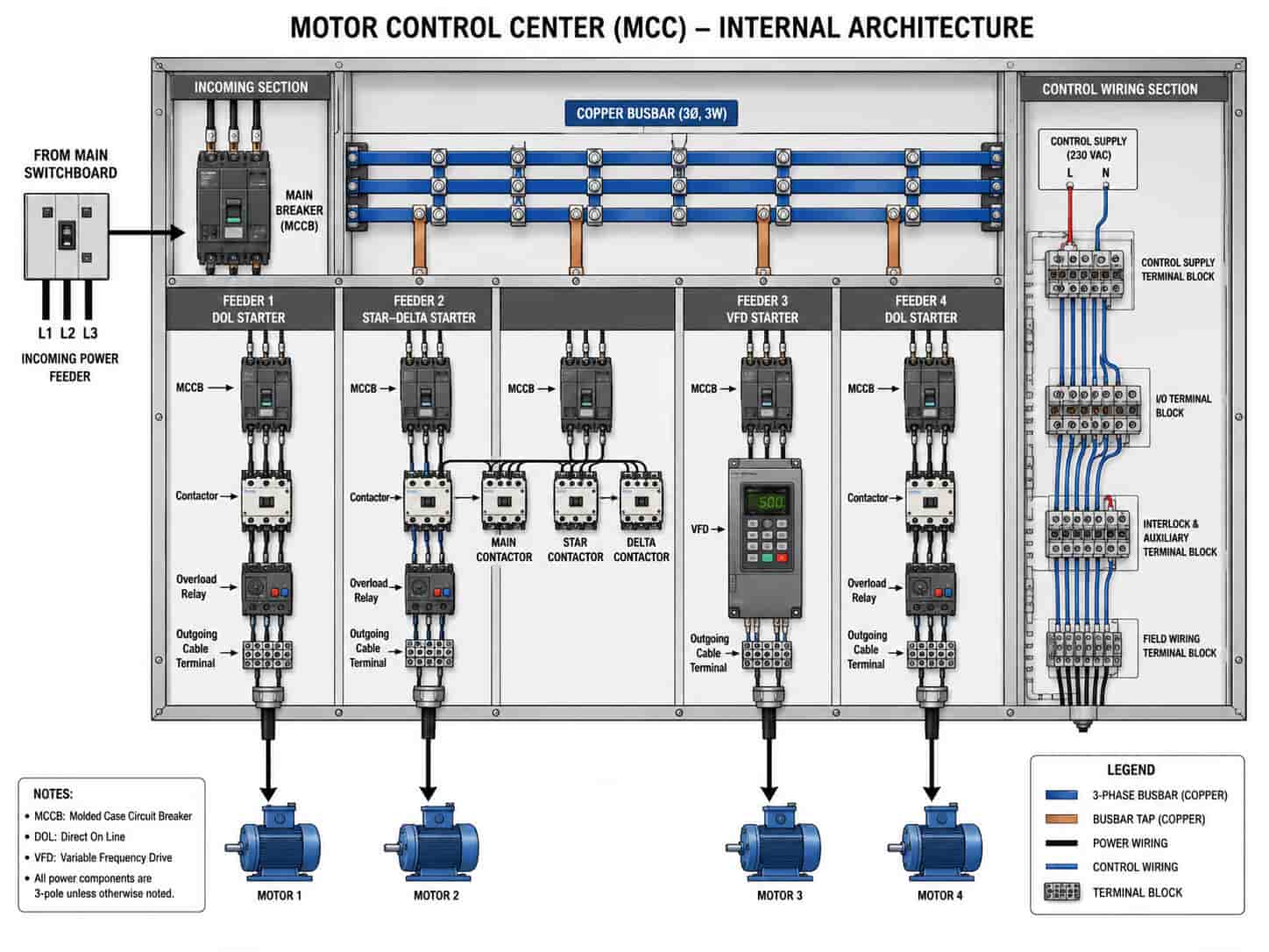
The motor control center (MCC) is the central procurement item for any plant with significant motorized equipment. Key specification parameters:
MCC Configuration
- Form of separation: Form 3b or Form 4 Type 6/7 — Form 4 preferred for operating plant maintainability
- Incoming section: ACB or MCCB rated for full MCC load, with earth fault protection
- Outgoing units: direct-on-line (DOL) starters for motors below approximately 7.5kW; star-delta or soft starters for larger motors; VFDs for variable-speed applications
- Busbar: copper busbar rated for maximum MCC demand current and system fault level
- IP rating: IP42 standard for indoor MCC rooms; IP54 for MCCs in plant areas
- Standard: IEC 61439-1/2 (low voltage switchgear assemblies)
Motor Starter Selection
Motor Cable Sizing
Motor feeder cables are sized based on motor full-load current (FLC) from the motor nameplate or IEC 60034 tables, with derating applied for installation conditions:
- Cable rating ≥ 125% of motor FLC for continuous duty motors (IEC 60364 requirement)
- Apply derating factors for grouping, ambient temperature, and installation method per IEC 60364-5-52
- Voltage drop calculation: confirm voltage drop to motor terminals does not exceed 5% of rated voltage under starting conditions
- For star-delta starters: cable between MCC and motor carries 58% of FLC during run — size on this basis, not DOL starting current
Note: For motors above 90kW, consult the motor supplier for minimum cable cross-section at the motor terminal box. Large motors have fixed terminal box sizes and cable entry glands — specifying a cable that is too large in diameter will not fit the motor terminal box without modification.
Earthing and Lightning Protection
Industrial plant earthing serves safety, equipment protection, and signal reference functions. Key requirements:
- Main earth electrode: driven earth rods or buried ring conductor at plant perimeter, sized to achieve design earth resistance (typically less than 1 ohm for industrial plants)
- Main earth bar (MEB): copper bar in main switchroom connected to earth electrode and all structural metalwork, transformer tank, MV switchgear frame, and LV switchboard earth terminal
- Equipment earth conductors: green/yellow insulated copper conductors from each MCC, distribution board, and motor frame to the nearest earth bar — sized per IEC 60364-5-54
- TN-S earthing: separate protective earth (PE) and neutral (N) conductors throughout the LV system — mandatory for industrial plants with VFDs and sensitive instrumentation
- Lightning protection: IEC 62305 risk assessment to determine whether air termination network and down conductors are required; bonding of all metallic structures to earth system
Key Point: In plants with VFDs, earth conductor sizing is critical. VFDs generate high-frequency earth leakage currents that require a low-impedance earth path — standard earth conductor sizing based on fault current alone may be inadequate. Specify 50% of the phase conductor cross-section as the minimum earth conductor for VFD motor circuits, or follow the VFD manufacturer’s earthing specification.
Hazardous Area Classification and ATEX Requirements
Industrial plants handling flammable gases, vapors, dusts, or fibers require electrical equipment and cables that meet hazardous area (ATEX or IECEx) requirements in classified zones:
- Zone 0 / Zone 20: continuous presence of flammable atmosphere — very restricted equipment selection; typically only intrinsically safe (Ex i) equipment permitted
- Zone 1 / Zone 21: flammable atmosphere likely in normal operation — Ex d (flameproof), Ex e (increased safety), Ex i, or Ex n equipment; cables must be appropriate for zone
- Zone 2 / Zone 22: flammable atmosphere unlikely in normal operation — Ex n (non-sparking) equipment acceptable; standard industrial cables acceptable where surface temperature is controlled
For cables in hazardous areas:
- Armored cable (SWA or braided) is generally required in Zone 1/2 to prevent mechanical damage that could create ignition sources
- Cable glands must be certified for the zone and Ex protection concept — confirm gland certification matches the equipment enclosure Ex certification
- Instrumentation cables in hazardous areas must use intrinsically safe (IS) barriers or galvanic isolators at the control panel end
Note: Hazardous area electrical procurement requires confirmation of zone classification drawings (Ex zone drawings) from the process engineer before any equipment or cable is specified. Supplying non-ATEX equipment into a classified zone is a safety and regulatory compliance issue — not a procurement preference.