The installation method for a power cable is not an afterthought — it is one of the primary inputs to the cable specification. Whether a cable is directly buried, pulled through duct, or laid on a cable tray determines which armoring is required, which derating factors apply to the current-carrying capacity calculation, and what the minimum burial depth or tray fill requirements are.
This guide covers the three main cable installation methods used in B2B industrial and infrastructure projects — direct burial, installation in duct or conduit, and above-ground cable tray and ladder rack — with the key requirements for each method, how each method affects the cable specification, and how to select the appropriate method for a given application.
Why Installation Method Drives Cable Specification
The relationship between installation method and cable specification works in both directions: the installation method determines what cable construction is required, and the cable construction available constrains which installation method is practical.
- Direct burial requires armored cable — SWA for multi-core, AWA for single-core — because the cable must resist soil pressure, rodent attack, and mechanical disturbance without the protection of a conduit or tray
- Duct installation allows unarmored cable — the duct provides mechanical protection — but the cable must be sized for the derating that applies to cables in enclosed conduit, which is lower than free-air rating
- Cable tray allows unarmored cable in most indoor industrial environments, with armored cable preferred for outdoor or high-mechanical-risk tray locations
- The current-carrying capacity of the cable changes significantly by installation method — a 95mm² XLPE cable in free air carries approximately 50% more current than the same cable buried directly in soil — so changing the installation method after the cable schedule is issued may require the cross-sections to be recalculated
Key Point: Confirm the installation method for every cable run before issuing the cable specification or purchase order. A cable schedule that specifies cross-sections without confirming installation method cannot be verified for thermal adequacy. The installation method determines both the cable type (armored or unarmored) and the current capacity used in sizing.
Direct Burial: The Most Common Underground Method
Direct burial — laying cable directly in a prepared trench without a duct or conduit — is the most widely used method for underground power cable installation in industrial plants, renewable energy projects, and infrastructure construction. It is the lowest-cost underground method when the cable route is unlikely to be disturbed after installation.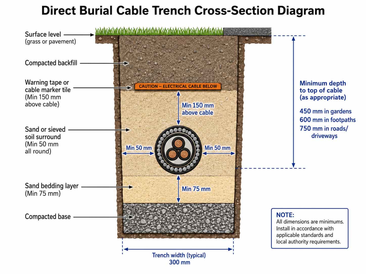
Trench Preparation
The trench must be prepared to provide a cable bed that supports the cable without point loading and allows heat dissipation:
- Trench width: minimum 300mm for a single cable; wider for multiple cables — allow at least one cable diameter of separation between cables to reduce mutual heating
- Trench base: remove rocks, rubble, and hard lumps that could damage the cable sheath or armor — the cable must not rest on sharp objects
- Sand bedding: a minimum 75mm layer of fine sand or sieved soil on the trench base before the cable is laid — fine sand fills voids under the cable and reduces point loading
- Sand surround: a minimum 50mm layer of fine sand or sieved soil placed over and around the cable after laying — do not backfill with excavated soil containing rocks until the sand layer is in place
Minimum Burial Depths
Minimum burial depths protect cables from mechanical disturbance by ground works, vehicle loading, and frost penetration. IEC 60364-5-52 and national standards specify minimum depths by location type:
Note: These are minimum depths — greater depth may be required in areas subject to deep cultivation (agricultural land), areas with corrosive or chemically active soil, or areas where future ground works are anticipated. Always confirm minimum burial depth with the project engineer and with any local utility authority requirements for grid-connected installations.
Warning Tape and Cable Marker Tiles
Cable marker tape and tiles are placed in the backfill above the cable to warn future excavators of the cable’s presence:
- Cable marker tape: orange or yellow plastic tape with printed warning text (‘ELECTRIC CABLE BELOW’ or equivalent in the local language), placed approximately 150mm above the top of the cable, extending the full length of the cable route
- Cable marker tiles: rigid plastic or concrete tiles placed above the warning tape — provide additional protection and a physical barrier to warn excavators before the cable is reached
- Route markers: surface markers at regular intervals (typically 50m and at every change of direction) and at each end of the cable run, indicating the cable route for future reference
Cable Armoring for Direct Burial
Direct-buried cables must be armored to provide mechanical protection:
- Multi-core cables (2-core to 5-core): specify SWA (steel wire armoring) — galvanized steel wires provide crush resistance, rodent resistance, and tensile strength for pulling during installation
- Single-core cables (large LV feeders and MV cables): specify AWA (aluminum wire armoring) — steel wire is not suitable for single-core AC cables due to induced armor currents
- Never directly bury unarmored cable without duct protection — see the earlier section on armoring selection
For a detailed explanation of SWA vs AWA armoring selection, see Armored vs Unarmored Cable: When to Specify SWA.
Current-Carrying Capacity for Direct Burial
The current-carrying capacity of a directly buried cable is lower than the same cable in free air because heat cannot dissipate as freely through soil as through air. The derating factors from IEC 60364-5-52 for buried cables depend on:
- Soil thermal resistivity: sandy dry soil reduces cable capacity more than moist clay — use site-specific soil data where available
- Burial depth: deeper burial means slightly more soil insulation around the cable — deeper cables have marginally lower capacity than shallower ones
- Grouping in trench: multiple cables in the same trench or parallel trenches share heat — apply grouping derating factors
For the complete current-carrying capacity calculation methodology including derating factors, see How to Calculate Cable Cross-Section: A Practical Sizing Guide.
Cable in Duct: HDPE Conduit and Duct Bank Systems
Installing cable in duct — drawing the cable through a pre-installed conduit or duct — provides protection equivalent to armored direct burial while allowing the cable to be pulled out and replaced in future without excavation. It is the preferred method for:
- Cable routes under roads, car parks, and paved areas where excavation in future would be disruptive and expensive
- Cable routes through building foundations, walls, and floor slabs
- Projects where future cable upgrades are anticipated — additional cables can be pulled through spare ducts without excavation
- Long cable routes where pulling unarmored cable through duct is easier than handling heavy armored cable
Duct Materials
The most common duct materials for underground cable installation are:
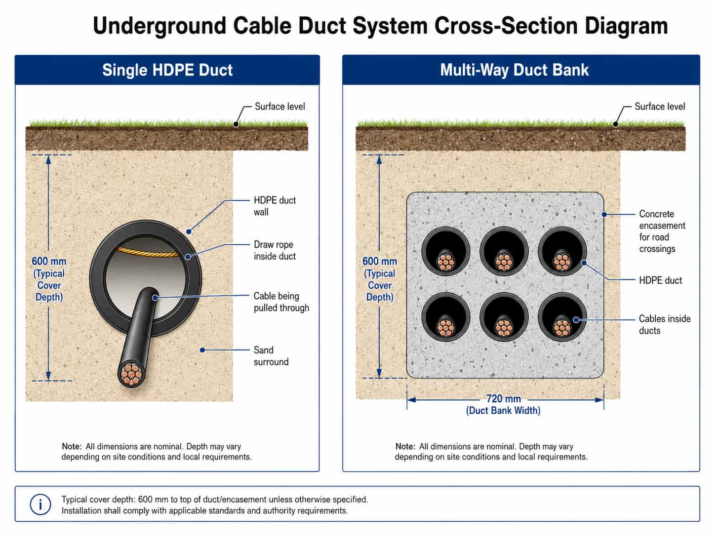
- HDPE (high-density polyethylene) duct: the standard for direct-buried underground cable ducts — flexible, chemically resistant, available in smooth-bore (for cable pulling) and corrugated (for increased flexibility) versions. Standard sizes: 50mm, 63mm, 75mm, 100mm, 110mm, and 160mm internal diameter.
- uPVC rigid conduit: used for shorter runs and within buildings — less suitable for long underground runs due to lower flexibility and more joints required
- Galvanized steel conduit: used in some industrial environments where mechanical protection of the duct itself is required — more expensive and subject to corrosion if moisture enters the conduit
- Fiber cement or concrete duct: used for high-traffic road crossings where greater mechanical strength is required — typically encased in concrete (duct bank) for road crossings
Duct Sizing for Cable Pulling
The duct internal diameter must be large enough to allow the cable to be pulled through without excessive friction. The standard rule is:
- Duct internal diameter ≥ 1.5 × cable outer diameter for single cable per duct
- For a 52mm OD armored cable: minimum duct ID = 52 × 1.5 = 78mm — specify 100mm ID HDPE duct
- Never fill a duct to more than 40% of its cross-sectional area with cable — multiple cables in one duct requires careful fill ratio calculation
- Always install a draw rope in each duct when the duct is laid — a draw rope installed after concrete encasement or backfill is extremely difficult to retrofit
Key Point: Install spare ducts alongside the active cable ducts as a minimum of 20% spare capacity. Spare ducts cost very little at installation time and allow future cables to be pulled without excavation. On road crossing duct banks, specify at least two spare ducts — the cost of excavating under a road to install a missed duct is many times the cost of the duct itself.
Duct Bank for Road and Railway Crossings
Where underground cables must cross under roads, railways, or other infrastructure that cannot be easily excavated, a duct bank is used:
- Multiple HDPE or uPVC ducts are arranged in a rectangular pattern (2×2, 2×3, 3×3, etc.)
- The duct arrangement is encased in concrete to provide mechanical strength and resist differential settlement
- The concrete encased duct bank is installed by open cut before road or railway construction, or by horizontal directional drilling (HDD) or pipe jacking for crossings under existing infrastructure
- Minimum concrete cover: 75mm over the outermost ducts for road crossings; 150mm for heavy-traffic or railway crossings
Current-Carrying Capacity in Duct
Cables installed in duct have lower current-carrying capacity than the same cable on a cable tray or in free air, because the duct restricts heat dissipation. The IEC 60364-5-52 installation method reference for cables in an enclosed duct is Method B (enclosed in conduit in thermally insulating wall) or Method D (underground in ducts, depending on the duct configuration).
For a 4-core 95mm² XLPE copper cable: approximate current ratings by installation method:
- Free air (Method E): approximately 238A
- Clipped to surface (Method C): approximately 249A
- In HDPE duct, buried (Method D): approximately 192A
- In conduit, enclosed (Method B): approximately 167A
This means that a cable sized for free-air installation will be undersized if changed to duct installation — the cross-section must be recalculated for the actual installation method.
Cable Tray and Ladder Rack Installation
Cable tray and ladder rack provide above-ground cable support for indoor industrial installations, substation cable rooms, and some outdoor applications. They are the standard installation method for cable runs inside industrial plants, process facilities, control buildings, and data centers.
Cable Tray Types
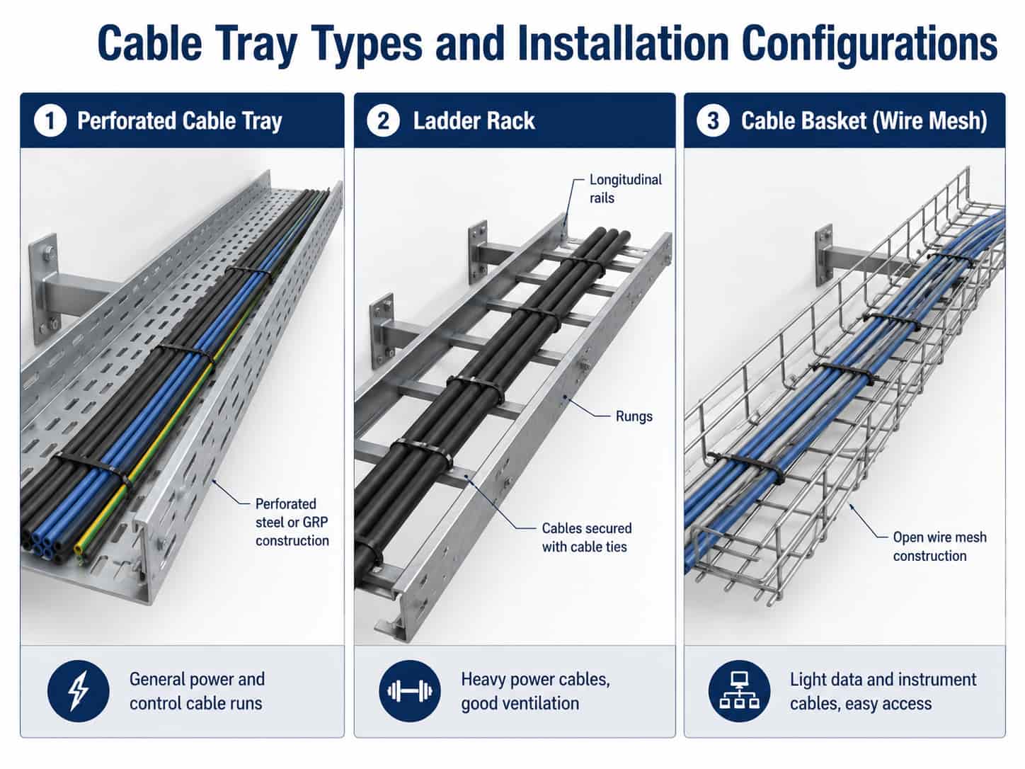
Cable trays are available in several configurations suited to different applications:
- Perforated cable tray: solid base with perforations for ventilation — the most common type for general power and control cable runs in industrial plants. Available in steel (hot-dip galvanized for outdoor, electro-galvanized for indoor) or GRP (glass-reinforced plastic for corrosive environments)
- Ladder rack: two longitudinal side rails connected by rungs at regular intervals — provides better ventilation than perforated tray, suitable for large power cables where heat dissipation is important. Cables are cable-tied to rungs at defined intervals
- Cable basket (wire mesh): open wire construction — lightweight, easy to cut and bend on site, suitable for light data and instrument cables. Not suitable for heavy power cables
- Solid-bottom tray: tray without perforations — used where cables need protection from dripping liquids or where electromagnetic screening of the cable run is required
Cable Tray Sizing and Fill Calculation
Cable tray must be sized to support the cables without exceeding the tray’s rated load capacity, and cable fill must be controlled to ensure adequate heat dissipation:
- Tray load capacity: sum the weight per metre of all cables on the tray (from cable datasheets) and confirm the total does not exceed the tray manufacturer’s rated load for the tray width and support span
- Support span: cable tray supports are typically spaced at 1.5–3m intervals for standard trays. Longer spans require heavier tray sections or intermediate supports
- Cable fill ratio: IEC 60364-5-52 specifies that cables on a tray should not be stacked more than one cable deep for thermal derating purposes — a single layer of cables touching side-by-side on a tray. Multiple layers require additional derating
- Tray width selection: allow 20–25% spare tray width for future cables — it is significantly cheaper to install a wider tray initially than to add a parallel tray run later
Tip: For industrial plants with dense cable runs, organize cables by voltage level on separate trays: high voltage (MV) on the topmost tray, then LV power, then control, then instrumentation on the lowest tray. This separation minimizes electromagnetic interference between power and signal cables and simplifies future maintenance identification.
Tray Material Selection
Installation Method Selection Checklist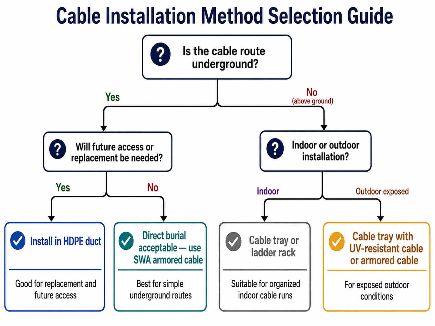
When preparing a cable specification or reviewing a cable schedule, confirm the following for each cable run:
- Installation method: direct burial, in duct (buried), in tray (indoor), in tray (outdoor), or in conduit (enclosed)
- Armoring requirement: SWA or AWA for direct burial; unarmored acceptable for duct and indoor tray; confirm for outdoor tray
- Burial depth: confirm against location type — footpath, road, agricultural, garden, or plant area
- Current-carrying capacity: recalculate using the correct installation method derating from IEC 60364-5-52 — do not use free-air ratings for buried or enclosed cables
- Sand bedding: specified in trench cross-section for direct buried cables
- Warning tape and markers: included in installation specification
- Duct sizing: confirm duct ID ≥ 1.5 × cable OD for each cable
- Spare ducts: minimum 20% spare duct capacity at road crossings and duct banks
- Tray fill: confirm single-layer tray fill for thermal derating purposes
- Cable fixing: cable ties, cleats, or trefoil formation cleating as required
Quotation Requirements
RichingPower supplies armored and unarmored power cables for direct burial, duct, and tray installation. When requesting a quotation, please specify the installation method for each cable type — it affects both the cable construction (armoring requirement) and the cross-section required for the current load. Please provide:
- Installation method: direct burial, in duct, indoor cable tray, or outdoor cable tray
- Cable specification: voltage grade, core count, conductor cross-section, insulation and sheath
- Armoring requirement: SWA (multi-core direct burial), AWA (single-core direct burial), or unarmored (duct/tray)
- Applicable standard: IEC 60502-1/2, BS 5467, AS/NZS 1429, or other
- Total quantity (meters), drum length, and delivery destination
Submit your cable specification via the RichingPower contact page. If you are unsure which armoring or cross-section is required for your installation method, provide the load current and installation conditions and our technical team will advise before preparing a quotation.
Conclusion
The installation method is the starting point for a complete cable specification — not an afterthought. Direct burial requires armored cable and sets the current-carrying capacity at the buried installation method rating; duct installation allows unarmored cable but carries a further derating penalty; cable tray in free air allows the highest current rating but requires tray sizing and fill management.
For B2B buyers reviewing cable schedules or writing cable specifications, confirming the installation method for every cable run before specifying cross-sections and armoring prevents the most common cable specification errors: undersized conductors calculated on free-air ratings for buried cables, and armored cable specified unnecessarily for duct-installed runs.
For armoring type selection (SWA vs AWA), see Armored vs Unarmored Cable: When to Specify SWA. For current-carrying capacity calculation with installation method derating, see
How to Calculate Cable Cross-Section: A Practical Sizing Guide. Contact RichingPower with your project cable schedule for a specification review and quotation.