
One of the most common questions in B2B cable procurement is: how do I know what cross-section I need? The answer depends on four factors — the load current, how the cable is installed, the ambient temperature and grouping conditions, and whether the cable is long enough for voltage drop to be a constraint.
This guide walks through the cable sizing process step by step, using IEC standards as the reference framework. It is written for procurement managers, project engineers, and B2B buyers who need to understand the sizing logic — either to write a specification, to check a supplier’s proposal, or to verify that a cable schedule produced by a designer is reasonable before ordering.
Note: Cable sizing for safety-critical installations should always be confirmed by a qualified electrical engineer. This guide explains the methodology and gives buyers the tools to understand and check sizing — it is not a substitute for professional engineering sign-off on a project specification.
Why Cable Cross-Section Matters
The cross-sectional area of a cable conductor (expressed in mm²) determines how much current the cable can carry continuously without the conductor temperature exceeding the insulation’s rated limit. Too small a cross-section and the cable overheats — insulation degrades, protection devices may not trip fast enough, and in severe cases fire results. Too large a cross-section and the cable is more expensive and heavier than necessary.
The sizing process is a balance between three constraints:
- Current-carrying capacity: the cable must carry the design load current without overheating
- Voltage drop: for long cable runs, the resistive voltage drop along the cable must stay within acceptable limits at the load terminals
- Short-circuit withstand: the cable must survive the fault current flowing until the protection device operates — this is typically checked by the protection engineer rather than the cable buyer
In practice, for most B2B industrial and commercial cable specifications, current-carrying capacity and voltage drop are the two constraints that determine the final cross-section. Short-circuit withstand is usually handled automatically by the protection design.
Step 1: Determine the Design Current (Ib)
The design current Ib is the maximum continuous current the cable is expected to carry under normal operating conditions. For different load types, Ib is calculated differently: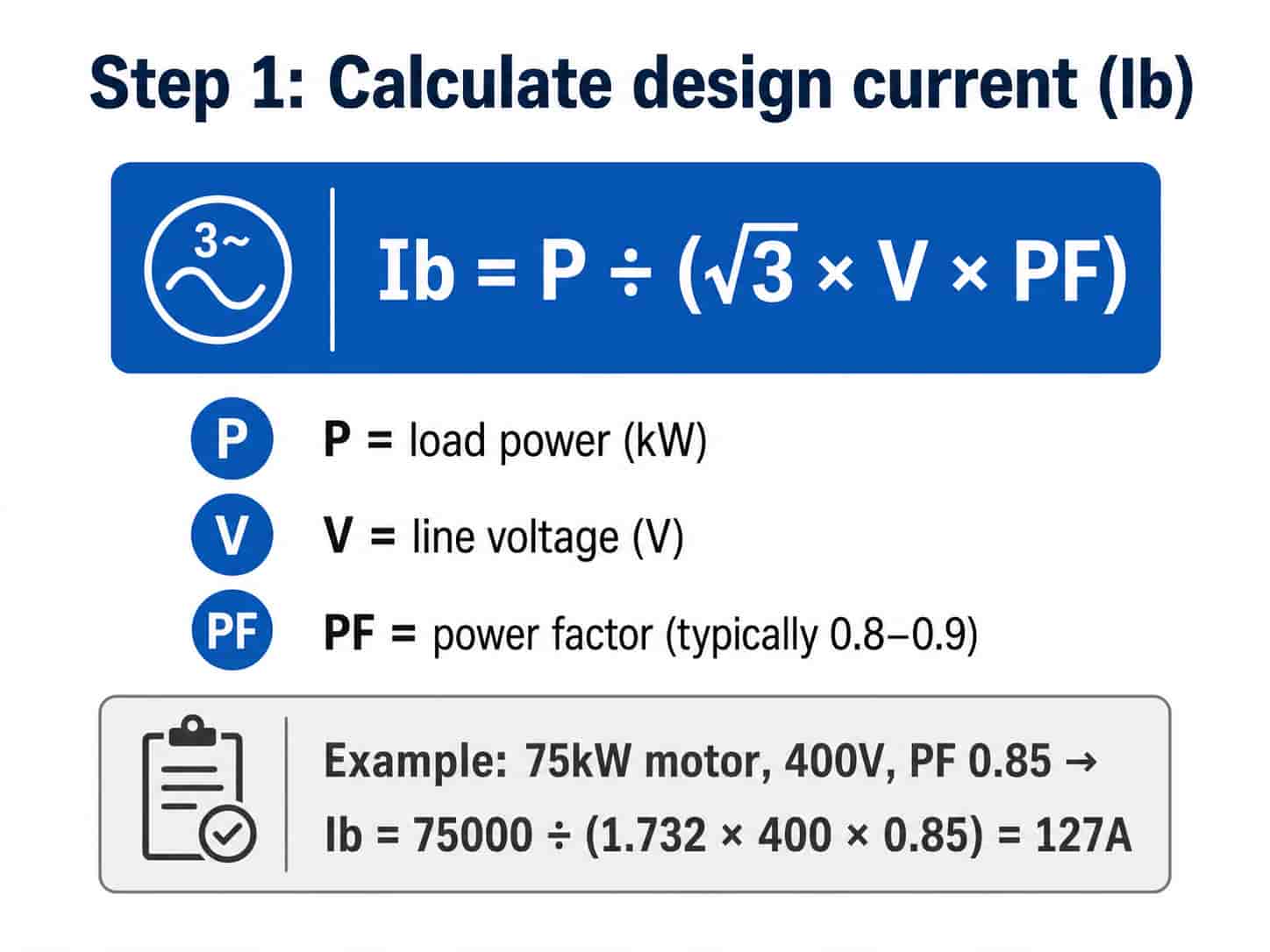
Motors (single motor feeder)
For a motor feeder, the design current is the motor’s full-load current (FLC), which can be read from the motor nameplate or calculated from the motor rated power:
- Three-phase motor: Ib = P ÷ (√3 × V × PF × η)
- P = rated motor power in watts (W)
- V = line-to-line supply voltage (V)
- PF = power factor (typically 0.80–0.90 for industrial motors)
- η = motor efficiency (typically 0.88–0.95 for modern IE3 motors)
- Example: 75kW motor, 400V, PF 0.85, efficiency 0.92 → Ib = 75000 ÷ (1.732 × 400 × 0.85 × 0.92) = 138A
Tip: For motor feeders, add a 25% margin to the calculated FLC when specifying the cable — motor cables are sized to 125% of FLC per IEC 60364-4-43 to account for starting current thermal effects and to match the motor protection device setting.
Distribution feeders (multiple loads)
For a feeder supplying multiple loads, the design current is the sum of the individual load currents multiplied by a diversity factor — typically 0.5–0.8 depending on how many loads are likely to operate simultaneously:
- Ib = (sum of individual load currents) × diversity factor
- Diversity factor of 1.0: all loads operate simultaneously at full load — use for safety-critical circuits or where simultaneous operation is confirmed
- Diversity factor of 0.7–0.8: typical for general industrial distribution where partial simultaneous loading is expected
- Diversity factor of 0.5–0.6: commercial or office distribution where load diversity is high
Transformer secondary feeders
For the main LV feeder from a transformer, the design current is the transformer’s full-load secondary current:
- Ib = transformer kVA rating × 1000 ÷ (√3 × secondary voltage)
- Example: 1000kVA transformer, 400V secondary → Ib = 1,000,000 ÷ (1.732 × 400) = 1443A
Step 2: Select the Tabulated Current Rating (It)
The tabulated current rating It is the maximum current a cable of a given cross-section can carry under standardized reference conditions — in free air at 30°C ambient temperature, with cables not grouped. These values are published in IEC 60364-5-52 (wiring installations) for each combination of cable type, conductor material, insulation, and installation method.
To select the correct tabulated value:
- Select the installation method reference letter from IEC 60364-5-52 Table B.52.1 (e.g. Method B = enclosed in conduit in thermally insulating wall, Method C = clipped to a surface, Method E = free air)
- Look up the tabulated current It for the required installation method and conductor type
- The selected cross-section must have It ≥ Ib before derating is applied
Key Point: The installation method letter changes the tabulated current significantly. The same 95mm² copper XLPE cable has a tabulated rating of approximately 238A on a cable tray in free air (Method E) but only about 167A when enclosed in conduit (Method B). Always use the tabulated value for the actual installation method — not the highest available value.
Step 3: Apply Derating Factors
The reference conditions for tabulated current ratings (30°C ambient, cables not grouped) rarely match the actual installation conditions. Correction factors — called derating factors — are applied to reduce the tabulated rating to the actual allowable current under real conditions.
Ambient Temperature Factor (Ca)
If the ambient temperature around the cable is higher than 30°C (for XLPE cable), the cable’s allowable current is reduced. IEC 60364-5-52 Table B.52.14 gives correction factors for different ambient temperatures:
- XLPE cable: reference temperature 30°C, rated conductor temperature 90°C
- Ca at 35°C = 0.96, at 40°C = 0.91, at 45°C = 0.87, at 50°C = 0.82
- PVC cable: reference temperature 30°C, rated conductor temperature 70°C
- Ca at 35°C = 0.94, at 40°C = 0.87, at 45°C = 0.79, at 50°C = 0.71
For installations in hot climates (Middle East, tropical regions) or near heat-generating equipment (furnaces, boiler rooms), ambient temperature correction is significant. A 50°C ambient reduces an XLPE cable’s allowable current to 82% of the tabulated value.
Grouping Factor (Cg)
When multiple cables run alongside each other on a tray or in a duct, they impede each other’s heat dissipation. The grouping factor Cg reduces the allowable current for cables in a bundle or group:
- 2 cables: Cg = 0.80
- 3 cables: Cg = 0.70
- 4 cables: Cg = 0.65
- 6 cables: Cg = 0.57
- 9 cables: Cg = 0.50
Note: These grouping factors apply when cables are touching or in close contact. Cables spaced by one cable diameter or more have reduced mutual heating — IEC 60364-5-52 provides separate factors for spaced installation. For large cable schedules with many circuits on a common tray, grouping derating is often the dominant factor in the sizing calculation.
Combining Derating Factors
The corrected allowable current Iz for the installed cable is:
- Iz = It × Ca × Cg
- The cable cross-section must be selected such that Iz ≥ Ib (design current)
- Example: 4-core 95mm² XLPE copper cable, Method C (clipped to surface), It = 220A, ambient 40°C (Ca = 0.91), 4 cables grouped (Cg = 0.65)
- Iz = 220 × 0.91 × 0.65 = 130A
- If design current Ib = 127A → 95mm² is adequate (130A ≥ 127A, margin is small but sufficient)
- If design current Ib = 135A → upsize to 120mm² (recalculate Iz for 120mm²)
Step 4: Check Voltage Drop
For longer cable runs, the resistive drop along the cable may cause the voltage at the load terminals to fall below acceptable limits — even if the cable is thermally adequate. Voltage drop is checked after the thermal sizing is completed.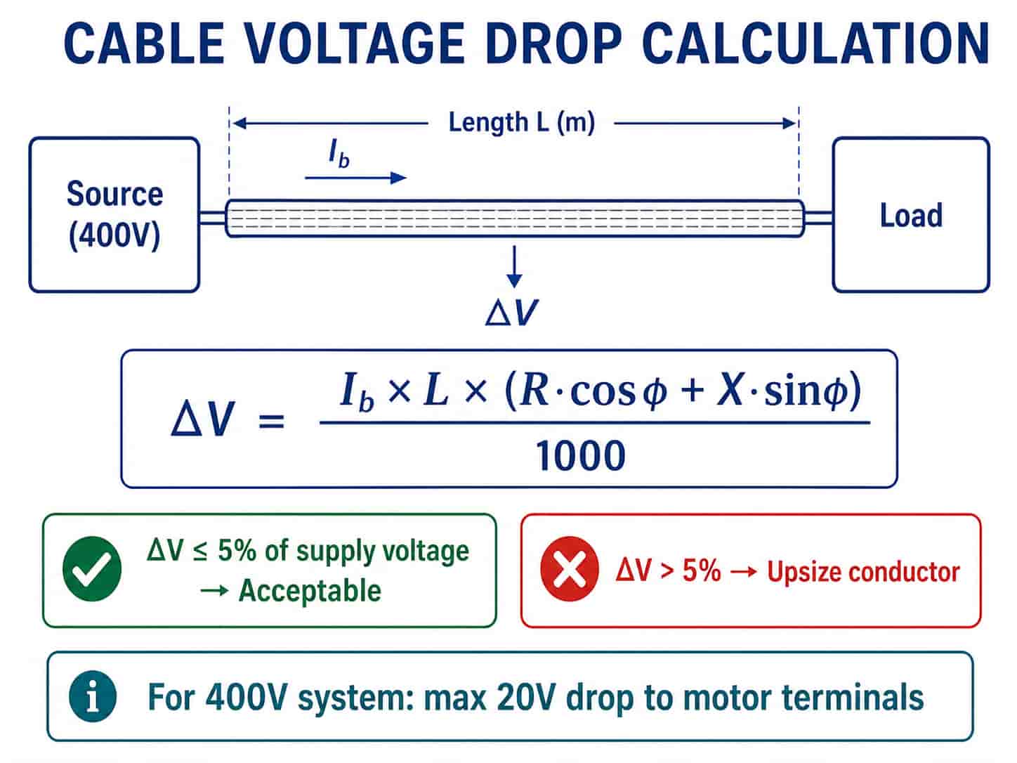
The voltage drop in a three-phase cable run is calculated as:
- ΔV (volts) = √3 × Ib × L × (r × cosφ + x × sinφ) ÷ 1000
- Ib = design current (A)
- L = cable run length (m)
- r = conductor resistance at operating temperature (mΩ/m per phase) — from cable datasheet
- x = conductor reactance (mΩ/m per phase) — from cable datasheet, typically 0.07–0.09 mΩ/m for LV cables
- cosφ = load power factor, sinφ = √(1 – cos²φ)
The percentage voltage drop is:
- ΔV% = ΔV ÷ nominal voltage × 100
- Acceptable limits: IEC 60364-5-52 recommends maximum 4% voltage drop from the supply point to the most remote outlet for lighting circuits, and 5% for other circuits
- For motor starters: some manufacturers specify a minimum voltage at the motor terminals during starting — check if a tighter limit applies
Key Point: Voltage drop is most likely to be the limiting factor on long cable runs supplying low-power loads. For a 100m run to a 10kW load, voltage drop may require a larger conductor than the thermal calculation alone. For a 10m run to a 200kW motor, thermal sizing dominates. Always check both constraints — they apply independently and the larger cross-section required by either constraint is the one to specify.
Worked Example: Sizing a Motor Feeder Cable
To illustrate the four-step process, here is a complete worked example:
Scenario: 90kW induction motor, 400V three-phase, power factor 0.85, motor efficiency 0.92. Cable run length 60m. Installation: clipped to surface (Method C). Ambient temperature 40°C. Cable runs with 3 other cables of similar size. Conductor: copper, XLPE insulation.
Step 1: Design current
- Ib = 90,000 ÷ (1.732 × 400 × 0.85 × 0.92) = 165A
- Apply 125% motor cable factor: Ib(design) = 165 × 1.25 = 207A
Step 2: Tabulated current
- Method C (clipped to surface), 4-core copper XLPE: select 150mm² → It = 261A from IEC 60364-5-52
Step 3: Apply derating
- Ca (40°C, XLPE) = 0.91
- Cg (4 cables grouped) = 0.65
- Iz = 261 × 0.91 × 0.65 = 154A
- 154A < 207A (Ib) → 150mm² is insufficient. Upsize to 185mm²
- 185mm² It = 300A → Iz = 300 × 0.91 × 0.65 = 177A
- 177A < 207A → still insufficient. Upsize to 240mm²
- 240mm² It = 340A → Iz = 340 × 0.91 × 0.65 = 201A
- 201A < 207A → marginally insufficient. Upsize to 300mm²
- 300mm² It = 380A → Iz = 380 × 0.91 × 0.65 = 225A
- 225A ≥ 207A → 300mm² passes thermal check
Step 4: Voltage drop check
- Using 300mm² copper: r ≈ 0.075 mΩ/m, x ≈ 0.074 mΩ/m at operating temperature
- ΔV = 1.732 × 165 × 60 × (0.075 × 0.85 + 0.074 × 0.527) ÷ 1000
- ΔV = 1.732 × 165 × 60 × (0.0638 + 0.039) ÷ 1000 = 1.76V
- ΔV% = 1.76 ÷ 400 × 100 = 0.44% — well within 5% limit
- Result: specify 4-core 300mm² copper XLPE cable (Method C, 60m run, 40°C ambient, 4 cables grouped)
Note: This worked example demonstrates why grouping derating is so significant — the required cross-section jumped from what might initially seem a 120mm² thermal calculation to 300mm² once ambient temperature and grouping are properly applied. Buyers should be cautious of cable schedules that do not show the derating calculation — a schedule showing only ‘load current’ without confirming the derated capacity may be undersized.
Common Sizing Mistakes to Avoid
- Using free-air tabulated values for buried or conduit installations — always match the tabulated value to the actual installation method
- Ignoring grouping derating for cables on a shared tray — a tray with 8 cables may require double the cross-section of an isolated cable for the same load
- Not checking voltage drop on long runs — thermal adequacy does not guarantee acceptable voltage at the load terminals
- Specifying cross-section without specifying installation conditions — a cable schedule that shows only ‘mm²’ without recording the installation method and ambient temperature cannot be verified
- Using the same cross-section for copper and aluminum feeders without adjusting for conductivity difference — aluminum requires approximately 1.6× the cross-section of copper for the same current
- Forgetting to apply the 125% factor for motor feeders — motor cables sized at exactly the FLC will be undersized for protection device coordination
The Sizing Checklist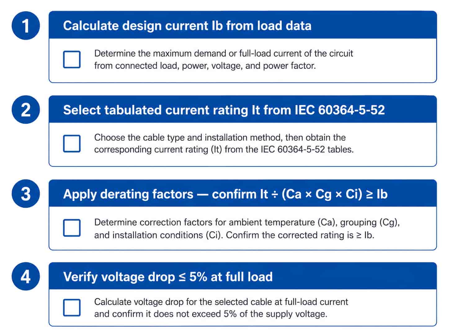
When providing a cable specification for a B2B inquiry, include the following sizing parameters to allow the supplier to confirm the cross-section is appropriate and to compare quotations on a like-for-like basis:
- Design current Ib (A) — the maximum continuous load current
- Installation method (IEC 60364-5-52 method letter or description)
- Ambient temperature at installation location (°C)
- Number of cables grouped on the same tray or in the same duct
- Cable run length (m) — for voltage drop check
- Load power factor (for voltage drop calculation)
- Maximum acceptable voltage drop (% of supply voltage)
- Conductor material: copper (Cu) or aluminum (Al)
- Insulation type: XLPE or PVC
Providing these parameters with the cable inquiry allows RichingPower to confirm the specified cross-section is correct, or to advise on a different cross-section if the sizing is found to be inadequate or oversized for the application.
Quotation Requirements
RichingPower supplies industrial power cables in a full range of cross-sections from 1.5mm² to 630mm² in both copper and aluminum conductors. To receive an accurate quotation confirming that the specified cross-section meets your installation requirements, please provide:
- Design current (A) and load type (motor, distribution feeder, transformer secondary)
- Installation method and ambient temperature
- Grouping conditions (number of cables on common tray or in duct)
- Cable run length and maximum acceptable voltage drop
- Conductor material, insulation type, armoring requirement, and voltage grade
- Applicable standard and total quantity
Submit your cable sizing requirement via the RichingPower contact page. If you are unsure of the correct cross-section, provide the load data and installation conditions and our technical team will advise on the appropriate sizing before preparing a quotation.
Conclusion
Cable cross-section sizing is a four-step process: calculate the design current, look up the tabulated current rating for the installation method, apply derating factors for ambient temperature and grouping, then verify that voltage drop is within limits for the run length. The cross-section selected must satisfy both the thermal constraint (derated current ≥ design current) and the voltage drop constraint independently.
For B2B procurement, understanding the sizing methodology allows buyers to write complete specifications, check existing cable schedules for adequacy, and compare supplier quotations on a technically consistent basis. A specification that includes design current, installation conditions, and cable run length gives suppliers all the information needed to confirm or adjust the cross-section — and gives buyers a basis for rejecting under-specified proposals.
For guidance on reading cable specification fields, see How to Read a Cable Specification Sheet. For current-carrying capacity reference values comparing copper and aluminum, see
Copper vs Aluminum Cable Conductor: Which Should You Specify?. Contact RichingPower with your project specification for a quotation.