Wind farm projects involve one of the most diverse and technically demanding electrical procurement packages in the renewable energy sector. A utility-scale wind farm combines high-voltage cable systems comparable to a small grid substation, specialist flexible cables inside each turbine tower, underground MV collection networks across the project site, and long-distance export cables connecting the farm to the grid — each with distinct specification requirements and installation constraints.
This guide covers the major electrical cable categories for onshore and offshore wind farm projects, the specific technical requirements of each cable type, the key differences between onshore and offshore procurement, the applicable standards, and what to include in a project quotation request.
Wind Farm Electrical Architecture
Understanding the electrical architecture of a wind farm is the starting point for organizing the cable procurement package by system zone.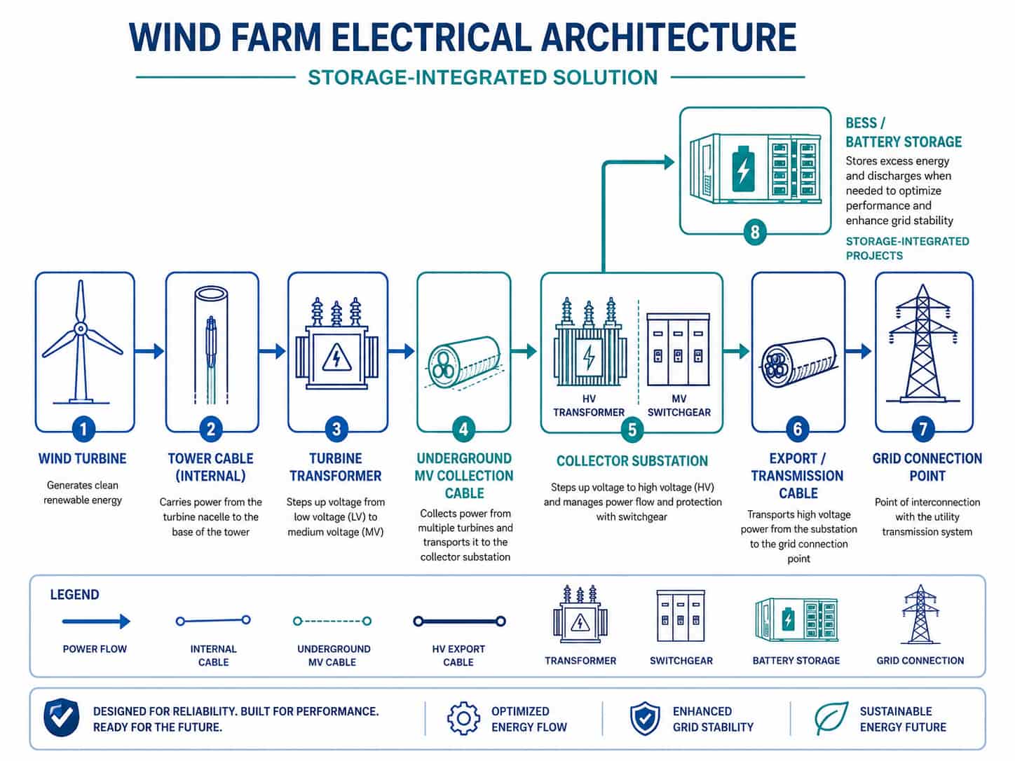
- Wind turbine generator (WTG): the generator inside each turbine nacelle produces AC power — typically at a relatively low voltage (690V or 1,000V) — which is immediately stepped up by a dedicated turbine transformer to the MV collection voltage
- Tower cable: flexible MV cable running inside the turbine tower from the nacelle-mounted transformer to the tower base — this cable must accommodate the continuous rotational movement of the nacelle and is one of the most specialist cable types in a wind farm
- Turbine transformer: pad-mounted or tower-integrated dry-type or oil-immersed transformer stepping up from turbine generator voltage to the MV collection voltage (typically 10kV, 20kV, 33kV, or 66kV)
- Array / collection cables: underground MV cables running from each turbine base to the next in a string configuration, collecting power from multiple turbines and routing it to the collector substation
- Collector substation: the on-site substation where the MV collection network is aggregated and stepped up to high voltage (HV) or extra-high voltage (EHV) for the export connection
- Export cable: the HV or EHV cable from the collector substation to the grid connection point — may be tens of kilometres for remote onshore projects or hundreds of kilometres for offshore projects
- Auxiliary and control cables: LV power and control cables throughout the turbine, nacelle, switchgear, and substation — LSZH in enclosed areas
Key Point: The MV collection voltage chosen for a wind farm significantly affects the cable procurement package. Higher collection voltages (33kV or 66kV vs 10kV) allow larger collection strings with fewer cables per string, reducing total underground cable length. However, the higher voltage requires thicker insulation and more complex terminations. The collection voltage is fixed by the electrical design — confirm it with the project engineer before specifying any array or collector cables.
Cable Types and Specifications by System Zone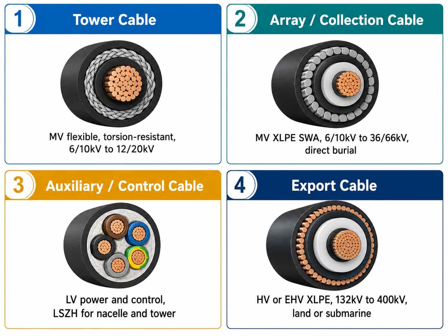
1. Tower Cable (Torsion-Resistant MV Flexible Cable)
The tower cable is the most technically specialist cable in a wind farm. It runs from the turbine transformer (in the nacelle or upper tower) down the inside of the turbine tower to the switchgear at the tower base. The turbine nacelle yaws (rotates) to track the wind direction — over the turbine’s 20–25 year operating life, this rotation accumulates millions of torsion cycles on the tower cable.
Critical specification requirements for tower cable:
- Voltage grade: typically 6/10kV, 12/20kV, or 20/35kV depending on collection voltage — match to turbine transformer secondary voltage
- Conductor: extra-flexible Class 5 or Class 6 stranded copper — fine strands for torsion resistance
- Insulation: EPR (ethylene propylene rubber) — superior flexibility at large cross-sections compared to XLPE, essential for torsion application
- Torsion class: specified in cycles at defined twist angle — typically 100,000–500,000 cycles at ±180° per IEC 60811 or turbine manufacturer specification
- Outer sheath: PCP (polychloroprene) or TPE — oil-resistant, flame-retardant for tower interior environment
- Screen: copper wire or braid screen for MV field control
- Core count: typically 3 cores (3-phase power) plus optional pilot and monitoring cores
- Flame retardance: IEC 60332-3 mandatory — tower is an enclosed vertical shaft
Key Point: Tower cable must be specified and tested for the specific torsion cycle requirement of the turbine model being installed. Different turbine manufacturers (Vestas, Siemens Gamesa, GE, Goldwind, Mingyang) specify different torsion requirements. Obtain the turbine manufacturer’s tower cable specification sheet and use it as the procurement reference — do not attempt to specify tower cable from first principles without the turbine OEM’s requirements.
2. Array / Collection Cables (Underground MV)
The array cable system carries power from individual turbine bases through the wind farm and to the collector substation. These are underground MV cables installed by direct burial or in duct, typically in strings connecting 6–12 turbines per feeder circuit.
Specification requirements:
- Voltage grade: 6/10kV, 12/20kV, 20/35kV, or 26/45kV depending on collection voltage — confirm U0/U format
- Conductor: copper or aluminum — aluminum increasingly used for larger cross-sections (150mm² and above) on long collection runs
- Insulation: XLPE with semi-conductive screens and copper tape metallic screen — standard MV construction to IEC 60502-2
- Armoring: SWA (multi-core cables) or AWA (single-core cables) for direct burial
- Outer sheath: PVC or HDPE — HDPE preferred for direct burial in wet or chemically active soil
- Cross-section: sized for peak string current plus derating for burial depth and soil thermal resistivity — range typically 70mm² to 400mm² depending on string length and turbine capacity
- Drum length: confirm maximum drum length against available drum handling equipment at site — large cross-section MV cable can weigh 4–6 kg/m, making long drums very heavy
- Standard: IEC 60502-2
The cross-section sizing for array cables must account for soil thermal resistivity at the installation site, burial depth, and any grouping of cables in the same trench. Wind farm sites in sandy or dry soil have higher thermal resistivity than clay or wet soil, requiring larger cable cross-sections for the same current. Always obtain a soil thermal resistivity survey before finalizing array cable sizing.
3. Auxiliary Power and Control Cables
The LV auxiliary power and control cable package for a wind farm covers all non-MV wiring within the turbine, nacelle, tower base switchgear, collector substation, and site infrastructure:
- Tower and nacelle power cables: 0.6/1kV XLPE or LSZH, for auxiliary loads including hydraulics, cooling, yaw drives, pitch systems, and lighting
- Tower and nacelle control cables: 300/500V multi-core, for PLC I/O, relay logic, and control circuits between nacelle and tower base
- Instrumentation cables: 4–20mA analogue and fieldbus, individually screened pairs, for wind speed, direction, vibration, and temperature sensors
- LSZH requirement: mandatory for all cables inside the tower and nacelle — enclosed fire environment
- IEC 60332-3 flame retardance: mandatory for all cables in tower and nacelle cable management systems
- Standard: IEC 60227 and IEC 60502-1 for power cables; IEC 60227 for control and instrumentation
4. Export Cable
The export cable connects the collector substation to the grid connection point. For onshore wind farms, the export cable is typically a land cable at 132kV or 220kV. For offshore wind farms, the export cable is a submarine HV cable at 132kV, 220kV, or 400kV.
- Voltage grade: 76/132kV, 127/220kV, or 230/400kV — determined by the grid connection agreement
- Conductor: large cross-section copper or aluminum — typically 400mm² to 1,600mm² for land export cables
- Insulation: XLPE — the only insulation material suitable for HV applications
- Standard: IEC 60840 (cables above 30kV up to 150kV) or IEC 62067 (cables above 150kV)
- Land export cable: installed in duct or direct burial, with SWA or AWA armoring
- Submarine export cable (offshore): multi-layer construction including water-blocking, PE sheath, armor, and serving — highly specialist product sourced from specialist submarine cable manufacturers
Note: Land export cables (above 30kV) and submarine export cables are not standard B2B catalogue products — they are engineered-to-order items with long manufacturing lead times (6–18 months for large projects) and specialist installation requirements. For most B2B project buyers, export cable procurement is managed separately from the array and auxiliary cable packages, often through specialist HV cable suppliers rather than standard industrial cable manufacturers.
Onshore vs Offshore Wind Farm Cable Differences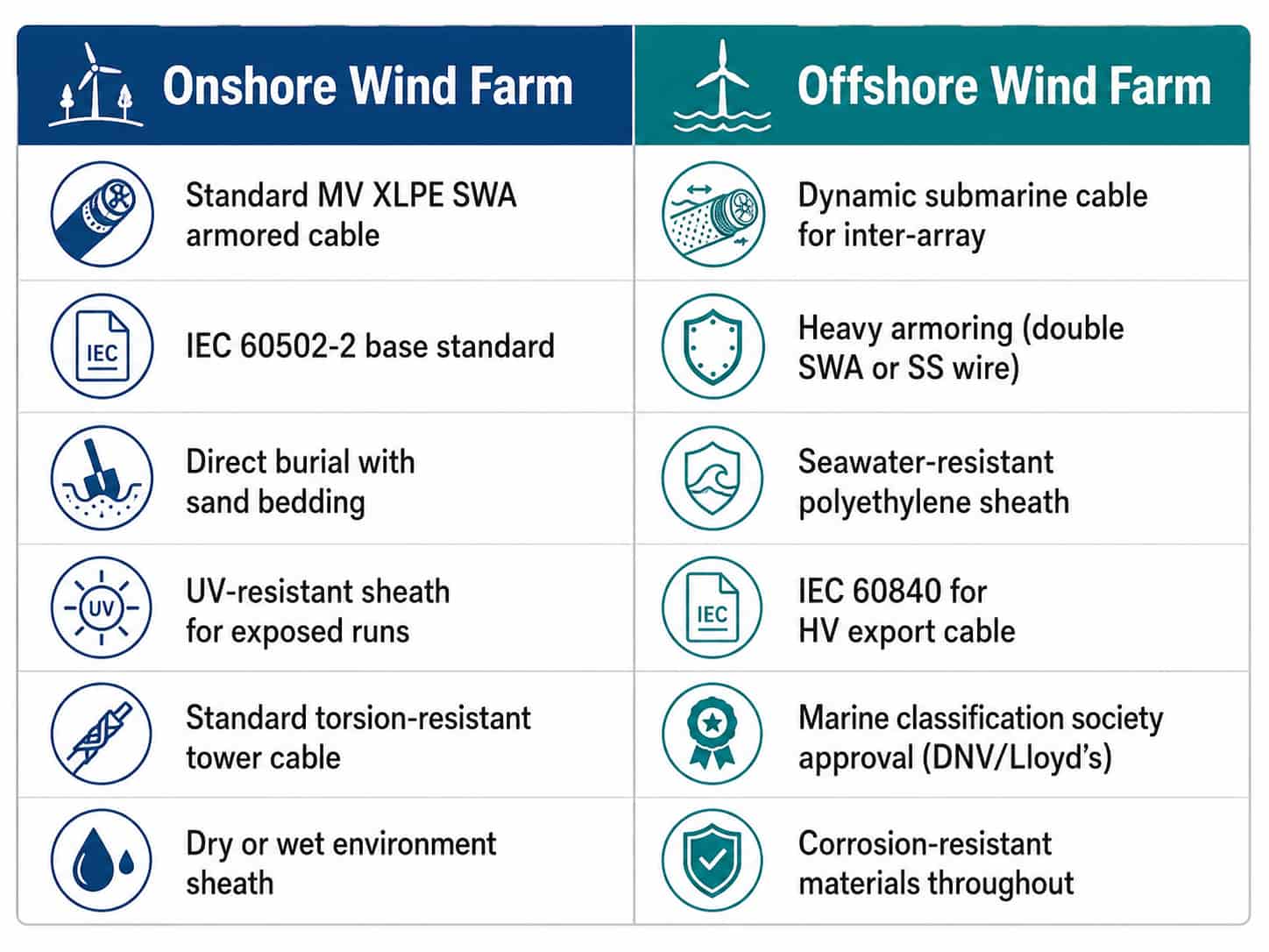
Note: Wind turbine manufacturers publish their own cable specifications for tower cables — the turbine OEM specification takes precedence over generic IEC standards for tower cable procurement. For Vestas, Siemens Gamesa, GE Vernova, Goldwind, and other major OEMs, request the relevant turbine-specific cable specification from the project’s turbine supplier before issuing a tower cable RFQ to cable manufacturers.
Soil Thermal Resistivity and Array Cable Sizing
Array cable sizing in wind farms is significantly affected by soil thermal resistivity — a measure of how easily heat dissipates from the buried cable into the surrounding soil. High thermal resistivity means heat is retained around the cable, limiting the current the cable can carry without exceeding the conductor temperature limit.
- Sandy dry soil: high thermal resistivity (1.5–3.0 K·m/W) — most wind farm sites in arid regions; requires larger cable cross-sections
- Clay or wet soil: lower thermal resistivity (0.7–1.2 K·m/W) — better heat dissipation; smaller cable cross-sections acceptable
- Standard burial depth for wind farm array cables: 1.0–1.2m below ground surface — deeper burial reduces ambient temperature effect but slightly increases thermal resistance of the soil column
- Trenching with sand bedding: fine sand backfill around the cable reduces effective thermal resistivity and is standard practice for wind farm array cable installation
The IEC 60287 standard provides the calculation method for buried cable current capacity accounting for soil thermal resistivity, burial depth, and cable grouping in a shared trench. For EPC buyers, the array cable cross-section selections should be confirmed against an IEC 60287 calculation using the site-specific soil thermal resistivity survey data — not from generic current capacity tables that assume standard soil conditions.
Tip: For wind farms in desert or semi-arid locations — Middle East, North Africa, parts of Australia — soil thermal resistivity is typically at the high end of the range. Cable cross-sections calculated without site-specific soil data frequently need to be upsized by one or two standard sizes when the actual soil resistivity data becomes available. Building a 15–20% contingency into the initial array cable MTO quantity avoids procurement delays when the cable schedule is revised after soil survey.
Wind Farm Cable Procurement Checklist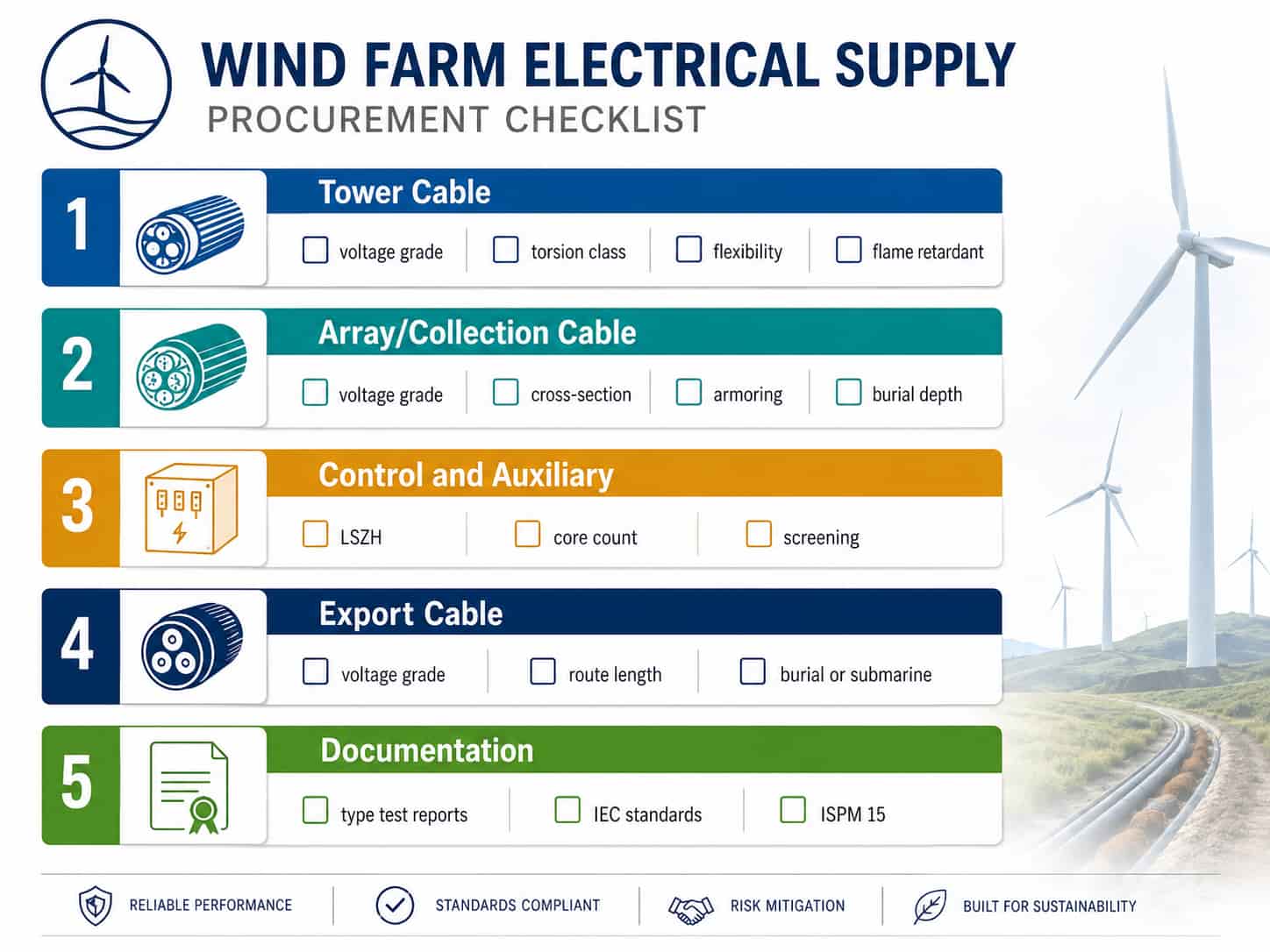
When preparing a wind farm cable inquiry, organize the specification by system zone and provide the following for each zone:
Tower Cable
- Turbine OEM and model — to obtain the turbine-specific cable specification
- Voltage grade (U0/U kV) at turbine transformer secondary
- Conductor cross-section (mm²) — from turbine OEM specification
- Torsion class: number of cycles and twist angle per turbine OEM specification
- Total number of turbines × cable length per turbine
- Applicable standard: IEC or turbine OEM specification reference
Array / Collection Cable
- Collection voltage level (kV) and voltage grade (U0/U)
- Conductor material (Cu or Al) and cross-section (mm²) for each string size
- Soil thermal resistivity survey data or assumed value for sizing
- Burial depth and installation method (direct burial or duct)
- Total cable quantity per cross-section (meters) and drum length
- Standard: IEC 60502-2
Control and Auxiliary Cables
- LSZH requirement confirmation for tower and nacelle cables
- Core count, conductor cross-section, and voltage rating for each cable type
- Screening requirement for instrumentation cables (IS pairs)
- Total quantity by cable type (meters)
- Standard: IEC 60227 or IEC 60502-1
Export Cable (if within scope)
- Export voltage (kV) and grid connection agreement reference
- Route length (km) and installation method (buried or submarine)
- Applicable standard: IEC 60840 or IEC 62067
- Note: HV and EHV export cables are engineered-to-order — contact separately from array cable procurement
Quotation Requirements
RichingPower supplies MV array collection cables, LV auxiliary power cables, control cables, and instrumentation cables for onshore wind farm projects. To receive an accurate project quotation, please provide:
- Project name, location, and total installed capacity (MW)
- Collection voltage (kV) and array cable voltage grade (U0/U)
- Array cable cross-section(s), conductor material, and quantity per cross-section
- Soil thermal resistivity data or assumed resistivity for sizing confirmation
- Tower cable: turbine OEM and model (we will advise on applicable specification)
- Auxiliary and control cable: types, core counts, and quantities
- Applicable standards and any certification requirements
- Delivery destination and target delivery date
Submit your wind farm cable specification via the RichingPower contact page. For projects with a cable schedule or MTO, attach the file for itemized quotation across all cable types and system zones.
Conclusion
Wind farm electrical procurement spans multiple cable categories — each with distinct technical requirements driven by the unique demands of turbine tower dynamics, underground collection systems, and long-distance export connections. The tower cable is the most specialist item and must be specified against the turbine OEM’s requirements. The array collection cable is the highest-volume item and must be sized against site-specific soil conditions. The auxiliary and control cables must be LSZH for all tower and nacelle installations.
Organizing the procurement by system zone — tower cable, array cable, control/auxiliary, and export cable — allows each category to be specified correctly and sourced from the most appropriate supplier. For EPC contractors and project buyers, early engagement with cable suppliers (at detailed design stage, not at construction mobilization) ensures production lead times can be met without programme delays.
For solar farm cable procurement which shares many similarities with wind farm array cable, see Solar Farm Cable and Electrical Supply: A B2B Procurement Guide. For BESS integration in wind-plus-storage projects, see
What Is a BESS? Industrial Energy Storage System Buyer’s Guide. Contact RichingPower with your wind farm cable schedule for a project quotation.