Control cables and instrumentation cables are both multi-conductor low-voltage cables used in industrial automation, process control, and plant electrical systems. They are often specified together on the same project cable schedule, but they serve fundamentally different circuit types and have distinct construction requirements.
Specifying instrumentation cable where control cable is adequate adds unnecessary cost. Specifying control cable where instrumentation cable is required causes signal noise, measurement errors, and in some cases system failures. This guide explains the difference between the two cable types, how each is constructed, what screening configuration each signal type requires, and how to write a correct specification for both.
What Is a Control Cable?
A control cable is a multi-conductor cable designed to carry electrical control signals — relay logic, contactor auxiliary circuits, PLC digital input/output, solenoid valve control, and motor starter auxiliary wiring. These circuits typically operate at 24V DC, 110V AC, or 230V AC and carry currents ranging from a few milliamps (digital I/O) to a few amperes (contactor coils and solenoid valves).
Key characteristics of control cable:
- Voltage rating: 300/500V is the standard rating for most industrial control cable; 450/750V for some applications requiring higher voltage withstand
- Core count: typically 2 to 61 cores depending on the number of circuits to be run in one cable — common configurations are 7-core, 12-core, 19-core, 27-core, and 37-core
- Conductor cross-section: 0.75mm², 1.0mm², 1.5mm², or 2.5mm² — selected based on the current carried and voltage drop requirements of the control circuit
- Insulation: PVC (standard) or LSZH for installations in enclosed spaces where fire performance is required
- Screening: unscreened for most control circuits; overall braid or foil screen for cables in electrically noisy environments
- Color coding: IEC 60446 — brown, black, gray, blue, green/yellow for the first five cores; subsequent cores numbered or color-coded per the applicable standard
- Standard: IEC 60227 (PVC-insulated cables) or IEC 60502-1 (for higher-rated control cables)
Key Point: Control cable is the correct specification for all circuits where the signal or control voltage is 24V DC or above, the circuit carries digital on/off signals rather than analogue measurement values, and signal noise is not a concern. Most PLC digital I/O, relay logic, and solenoid valve wiring falls into this category.
What Is an Instrumentation Cable?
An instrumentation cable is a multi-conductor cable specifically designed to carry low-level analogue signals — 4–20mA current loops, thermocouple signals (millivolt range), RTD (resistance temperature detector) signals, and digital fieldbus communications such as HART, Foundation Fieldbus, and PROFIBUS. These signals are at a much lower level than control signals, making them susceptible to electromagnetic interference (EMI) from nearby power cables, VFDs, motor starters, and other sources of electrical noise.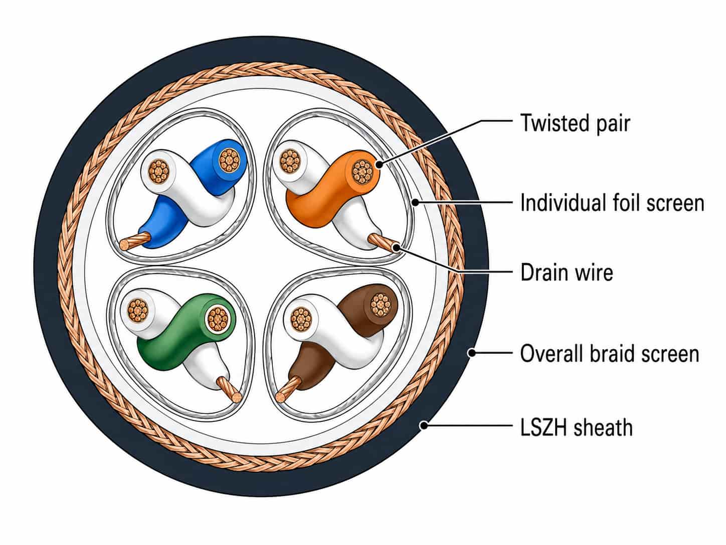
Key characteristics of instrumentation cable:
- Voltage rating: typically 300V — instrumentation signals operate at low voltage and current, so the voltage rating requirement is lower than control cable
- Construction: twisted pairs (or triads for 3-wire RTD circuits) — twisting cancels out induced noise by ensuring that both conductors pick up equal amounts of interference, which cancels at the receiving end
- Conductor cross-section: 0.5mm², 0.75mm², or 1.5mm² — small cross-section is adequate because signal currents are very low (typically under 20mA for 4–20mA loops)
- Individual pair screening: each pair has its own foil (aluminum-polyester) screen and drain wire — provides EMI shielding specific to that signal pair, preventing crosstalk between channels in the same cable
- Overall screen: a second screen (foil or braid) over all pairs — provides additional shielding against external EMI sources
- Drain wire: a bare or tinned copper conductor running alongside the foil screen — provides a low-resistance connection point for earthing the screen at the control panel
- Insulation: PVC or LSZH — LSZH mandatory in enclosed process areas and offshore installations
- Standard: IEC 60227 for PVC; project-specific or manufacturer specification for detailed construction requirements
Key Point: The twisted pair construction and individual screening of instrumentation cable are not optional features — they are the technical mechanisms that allow low-level analogue signals to be transmitted over long cable runs in electrically noisy industrial environments. Substituting control cable for instrumentation cable on 4–20mA analogue circuits will result in noise on the signal that manifests as measurement instability, erratic readings, or process control errors.
Screening: The Critical Difference
The most important difference between control cable and instrumentation cable is the screening configuration. Understanding how screening works helps buyers specify the correct configuration for each signal type.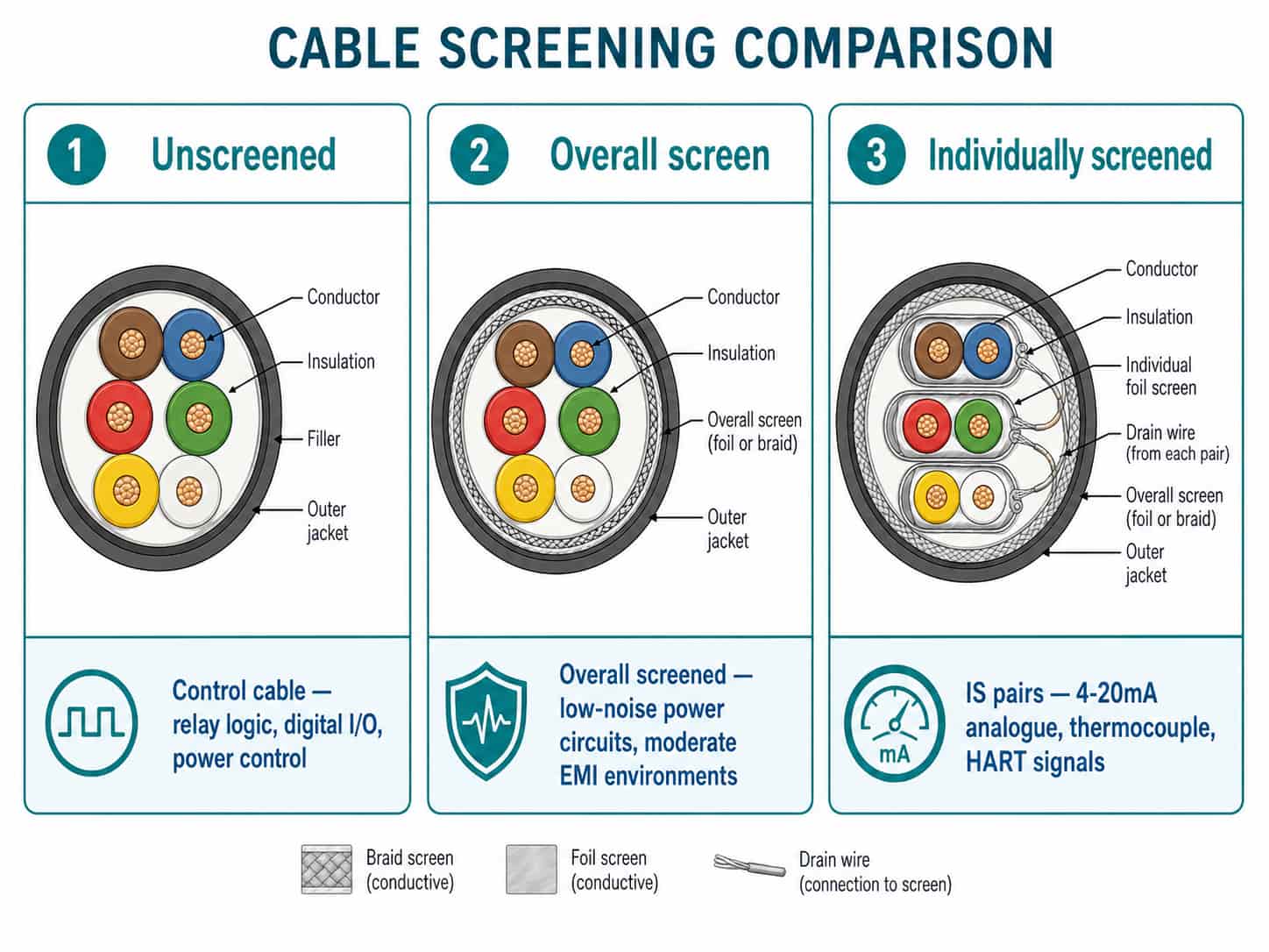
Unscreened Cable
An unscreened cable has no metallic screen layer. It provides no EMI shielding. Unscreened control cable is suitable for:
- Relay logic and contactor auxiliary circuits — the high signal levels (110V or 230V AC) are not significantly affected by EMI
- PLC digital input/output (DI/DO) — 24V DC digital signals with sufficient noise margin to tolerate EMI without error
- Motor starter auxiliary wiring — power circuit wiring where signal integrity is not the concern
- Emergency stop and safety relay circuits — high-voltage digital circuits with high noise margin
Overall Screen (OS)
An overall screen is a single metallic screen (foil or braid) applied over all conductors in the cable. It provides shielding against external EMI for the cable as a whole, but does not prevent crosstalk between individual pairs within the cable.
Overall screen is suitable for:
- Control circuits in environments with moderate EMI — near VFDs or large motors where some shielding is needed
- Digital communication cables where all conductors carry the same signal and crosstalk between pairs is not a concern
- Multi-core cables carrying multiple circuits of the same type where channel-to-channel isolation is not required
Individually Screened Pairs (IS)
Individually screened pairs (IS) provide a separate foil screen and drain wire for each signal pair in the cable. This configuration provides both EMI shielding from external sources and isolation between individual pairs within the cable — preventing crosstalk between channels.
Individually screened pairs are required for:
- 4–20mA analogue signal circuits — the standard for process instrumentation
- Thermocouple circuits — millivolt-level signals that are extremely sensitive to EMI and crosstalk
- RTD circuits — low-resistance signals sensitive to both EMI and leakage between adjacent circuits
- HART communication — the 1200/2200 Hz HART signal superimposed on the 4–20mA loop requires individual pair screening for reliable communication over long cable runs
- Foundation Fieldbus and PROFIBUS — digital fieldbus signals that require controlled impedance and screened pairs for reliable communication
Key Point: IS pairs are the standard for all process instrumentation in industrial plants. If a project datasheet or instrument data sheet specifies ‘individually screened pairs’, this is a firm requirement — the number of IS pairs, the screen type (foil or braid), and the drain wire must all be confirmed with the supplier. A multi-pair cable where all pairs share one overall screen does not meet the IS pairs requirement.
Screen Earthing: How to Connect the Screen
The effectiveness of cable screening depends entirely on how the screen is earthed. An incorrectly earthed screen provides little or no shielding and may actually make noise worse by acting as an antenna.
Single-Point Earthing (Recommended for Analogue Signals)
For 4–20mA analogue and thermocouple circuits, earth the screen at one end only — typically at the control panel or marshalling cabinet end. This prevents earth loop currents from flowing through the screen, which would add noise to the signal.
- Connect the drain wire to the screen terminal block at the control panel end
- Leave the drain wire disconnected (floating) at the field instrument end
- Apply this rule to every individually screened pair — each pair’s drain wire connected at the panel end, floating at the field end
Both-End Earthing (For Overall Screen Against RF Interference)
For cables in environments with high-frequency interference (near radio transmitters, VFDs), earthing the overall screen at both ends provides better shielding against high-frequency EMI. However, this creates an earth loop that can introduce low-frequency (50/60Hz) noise — accept this trade-off only when HF interference is the dominant problem and the 50Hz noise is within acceptable limits.
Note: Screen earthing is an installation decision, not a cable procurement decision. However, procurement and installation must be coordinated — the cable supplier must confirm that each individually screened pair has its drain wire accessible for separate connection at the panel end. Multi-pair cables where the drain wires are connected together internally before the outer sheath cannot implement correct single-point earthing.
Conductor Sizing for Control and Instrumentation Cables
Conductor cross-section selection for control and instrumentation cables is simpler than for power cables because current levels are low and voltage drop is rarely the limiting factor.
Selection Checklist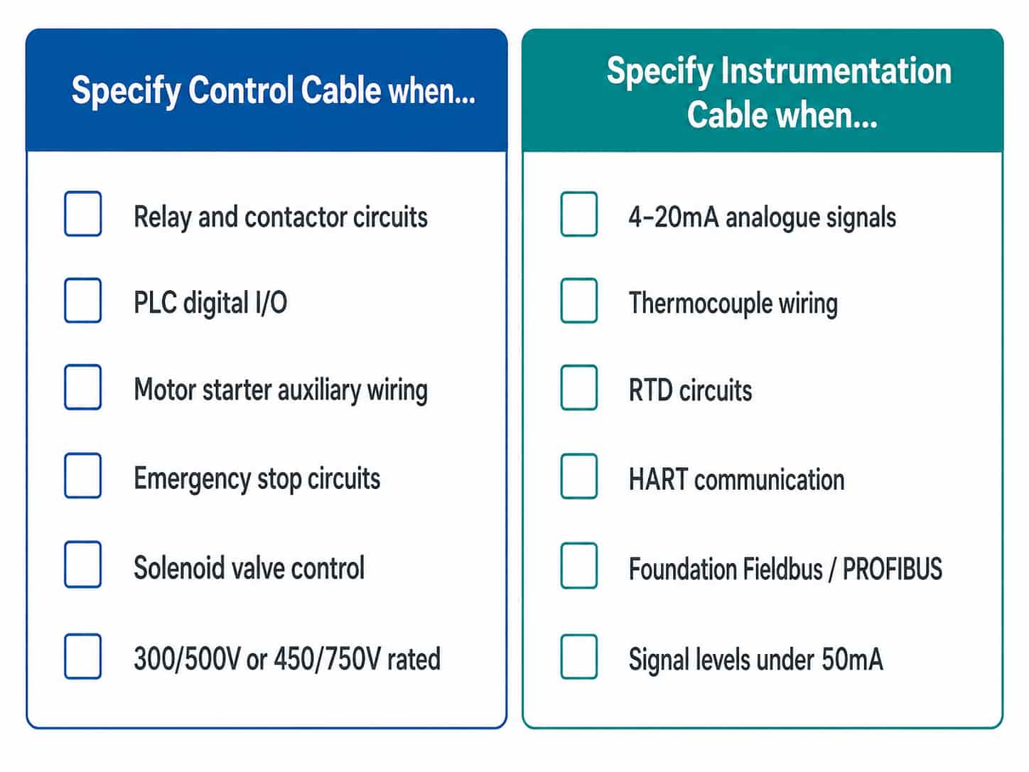
Use the following checklist when specifying control or instrumentation cable for a project:
- Identify the signal type for each cable run: relay/digital (→ control cable) or analogue/fieldbus (→ instrumentation cable)
- Confirm the operating voltage: 300/500V for control cable; 300V for instrumentation cable
- Determine screening requirement: unscreened, overall screen, or individually screened pairs
- Select conductor cross-section based on current, voltage drop, and terminal block compatibility
- Determine core count or pair count and grouping logic (same voltage, same signal type)
- Specify LSZH sheath if installation is in enclosed, occupied, or fire-sensitive areas
- Confirm armoring requirement: SWA for direct burial or high mechanical risk; unarmored for cable tray
- Specify applicable standard: IEC 60227, IEC 60502-1, or project/customer specification
- Confirm drain wire accessibility in IS pair cables
- State total quantity in meters and preferred drum length
Quotation Requirements
RichingPower supplies control cables and instrumentation cables for industrial, process, and infrastructure projects. To receive an accurate quotation, please provide:
- Cable type: control cable or instrumentation cable (IS pairs or overall screen)
- Core count (control cable) or number of pairs/triads (instrumentation cable)
- Conductor cross-section (mm²)
- Screening configuration: unscreened, overall screen, or individually screened pairs with drain wire
- Voltage rating: 300/500V (control) or 300V (instrumentation)
- Insulation and sheath material: PVC or LSZH
- Armoring requirement: SWA, AWA, or unarmored
- Applicable standard: IEC 60227, IEC 60502-1, or project specification
- Total quantity (meters), drum length, and delivery destination
Submit your cable specification via the RichingPower contact page. For projects with a mixed cable schedule including both control and instrumentation cable types, attaching the schedule allows itemized quotation across all cable types and configurations.
Conclusion
Control cable and instrumentation cable are distinct products with different construction, screening, and signal compatibility requirements. The key decision driver is the signal type: relay, digital, and power control circuits use unscreened or overall-screened control cable; analogue measurement, thermocouple, RTD, and fieldbus circuits require individually screened pair instrumentation cable.
Specifying the correct cable type from the outset — based on the instrument and control system datasheets — prevents signal noise problems, protects measurement accuracy, and avoids costly re-wiring during commissioning. A complete cable specification for either type should include core count or pair count, conductor cross-section, screening configuration, drain wire arrangement, sheath material, voltage rating, and applicable standard.
For guidance on specifying LSZH and other sheath properties, see XLPE vs PVC Cable Insulation: A Practical Selection Guide. For oil and gas projects where IS cable and blue sheath requirements apply, see
Oil and Gas Power Cable: Procurement Guide for Upstream and Offshore Projects. Contact RichingPower with your project cable schedule for a comprehensive quotation.